Method and device for controlling asymmetric flatness of oriented silicon steel

A technology of oriented silicon steel and flatness, which is applied in the field of control of asymmetric flatness of oriented silicon steel, can solve the problem of increasing the cut loss rate of strip steel in downstream production lines, the inability to effectively control the asymmetric flatness of silicon steel, and poor control accuracy And other issues

Active Publication Date: 2019-12-20
BEIJING SHOUGANG CO LTD
View PDF6 Cites 2 Cited by
  • Summary
  • Abstract
  • Description
  • Claims
  • Application Information

AI Technical Summary

Problems solved by technology

[0004] In view of the problems existing in the prior art, the embodiment of the present invention provides a method and device for controlling the asymmetric flatness of oriented silicon steel, which is used to solve the problem in the prior art that the asymmetric flatness of silicon steel cannot be effectively controlled, resulting in The control accuracy of the lateral thickness difference of the strip cannot be ensured, which leads to a decrease in the yield of silicon steel, and also increases the technical problem of the strip loss rate of the downstream production line

Method used


Image

  • Method and device for controlling asymmetric flatness of oriented silicon steel
  • Method and device for controlling asymmetric flatness of oriented silicon steel
  • Method and device for controlling asymmetric flatness of oriented silicon steel

Examples


Embodiment 1

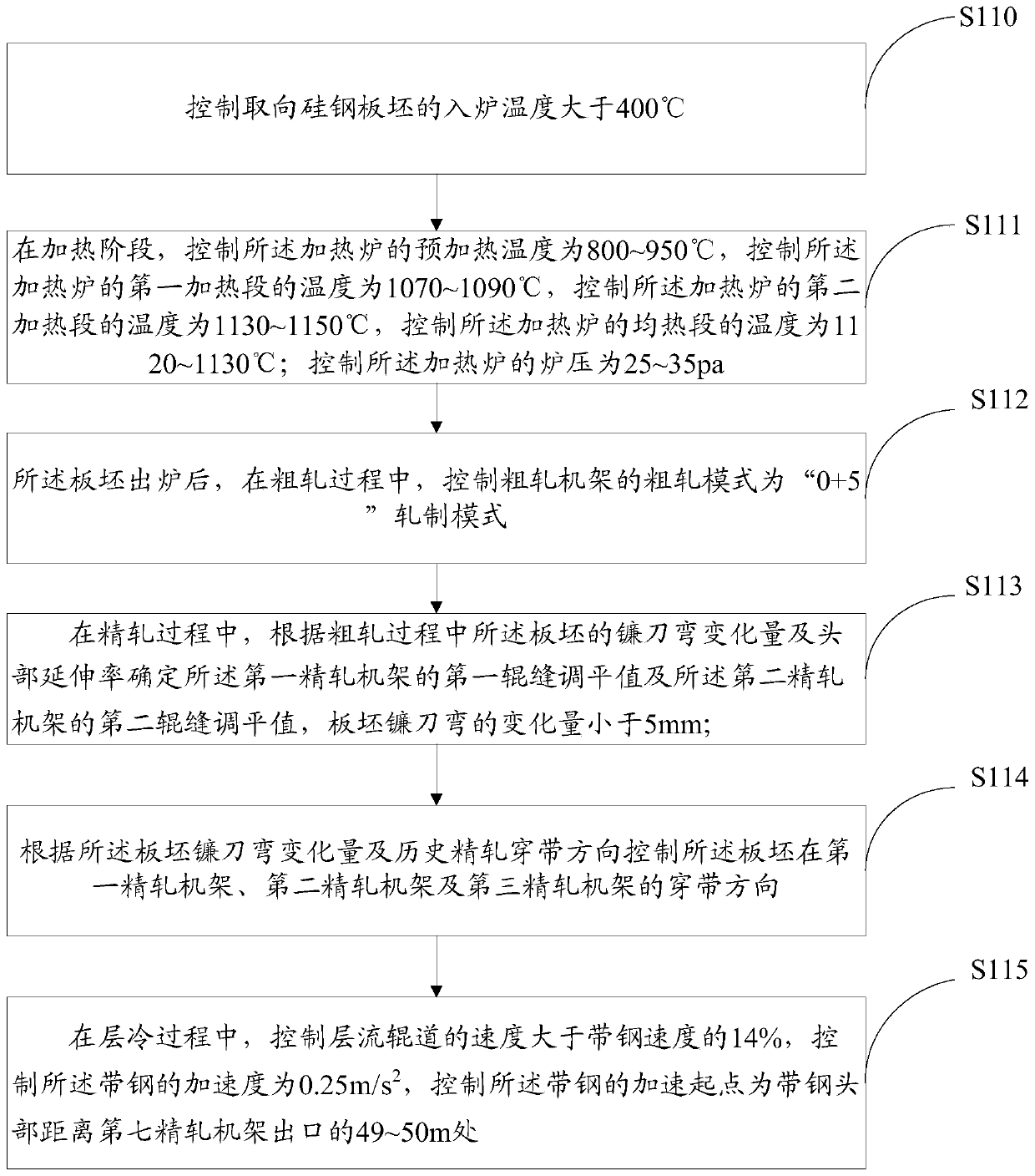
[0038] This embodiment provides a method for controlling the asymmetric flatness of grain-oriented silicon steel, such as figure 1 The methods shown include:

[0039] S110, controlling the furnace entry temperature of the oriented silicon steel slab to be greater than 350°C;

[0040] In order to reduce the blockage rate of asymmetric flatness of oriented silicon steel, control the furnace temperature of oriented silicon steel slab to be higher than 350°C. If hot charging and direct loading cannot be guaranteed; within 5°C. In this way, the asymmetric flatness blocking rate of grain-oriented silicon steel can be reduced by more than 15%.

[0041] S111. In the heating stage, control the preheating temperature of the heating furnace to be 800-950°C, control the temperature of the first heating section of the heating furnace to be 1070-1090°C, and control the temperature of the second heating section of the heating furnace. The temperature is 1130-1150°C, the temperature of the...

Embodiment 2

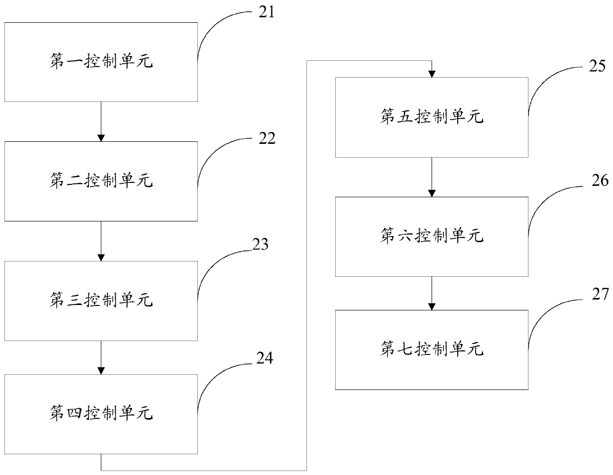
[0075] This embodiment provides a control device for the asymmetric flatness of grain-oriented silicon steel, such as figure 2 As shown, the device includes: a first control unit 21, a second control unit 22, a third control unit 23, a fourth control unit 25, a fifth control unit 26 and a sixth control unit 27; wherein,

[0076] In order to reduce the blockage rate of asymmetric flatness of oriented silicon steel, the first control unit 21 is used to control the temperature of the oriented silicon steel slab to be higher than 350°C. Keep warm, and control the difference between furnaces within 5°C. In this way, the asymmetric flatness blocking rate of grain-oriented silicon steel can be reduced by more than 15%.

[0077]In the heating stage, the heating process of the oriented silicon steel slab needs to be slow, the slab outlet temperature is strictly controlled at 1122-1128°C, and the temperature difference of each slab should be eliminated in the second heating section of...

Embodiment 3

[0101] In actual application, when rolling oriented and high-grade non-oriented silicon steel on the 1580 hot continuous rolling production line of Shougang Qiangang, the specific implementation is as follows:

[0102] Control the temperature of the oriented silicon steel slab into the furnace to be greater than 350°C. In the heating stage, control the temperature of the preheating section to 850°C; the temperature of the first heating section to 1090°C, the temperature of the second heating section to 1140°C, The temperature is 1130°C; the furnace pressure of the control furnace is 26pa.

[0103] In order to reduce the temperature drop in the rough rolling process, after the slab is released from the furnace, during the rough rolling process, the rough rolling mode of the rough rolling stand is controlled as "0+5" rolling mode; here, the rough rolling stand includes the first rough rolling stand and the second roughing stand; the "0+5" rolling mode includes: the first roughin...


PUM


Abstract

The invention provides a method for controlling asymmetric flatness of oriented silicon steel. The method comprises the steps of controlling charging temperature of an oriented silicon steel slab to be greater than 350 DEG C, controlling preheating temperature to be 800-950 DEG C, controlling temperature of a first heating zone to be 1070-1090 DEG C, controlling temperature of a second heating zone to be 1130-1150 DEG C, and controlling temperature of a soaking zone to be 1120-1130 DEG C; controlling furnace pressure to be 25-35 pa; controlling a rough rolling mode to be a '0+5' rolling mode;determining roll gap leveling values of a first finish rolling rack and a second finish rolling rack, wherein variation amount of slab camber is less than 5 mm; controlling threading directions of theslab on the first finish rolling rack, the second finish rolling rack and a third finish rolling rack; and in the layer cooling process, controlling speed of a laminar flow roller table to be greaterthan 14% that of strip steel, controlling accelerated speed of the strip steel to be 0.25 m/s<2>, and controlling acceleration starting point of the strip steel to be located in the position where ahead of the strip steel is 49-50 m away from an outlet of a seventh finish rolling rack.

Description

technical field [0001] The invention relates to the technical field of hot rolling, in particular to a method and device for controlling the asymmetric flatness of grain-oriented silicon steel. Background technique [0002] With the development and progress of the silicon steel industry, the requirements for the thickness control precision of silicon steel raw materials are getting higher and higher. The greater the lateral thickness difference of silicon steel, the lower the lamination coefficient of the iron core, and every 1% reduction in the lamination coefficient is equivalent to a 2% increase in iron loss and a 1% reduction in magnetic induction. In the increasingly fierce silicon steel market environment, it is necessary to improve the accuracy of the lateral thickness difference of the silicon steel sheet. [0003] The transverse thickness difference is mainly determined by the wedge shape and convexity of the strip, while the wedge shape is mainly determined by the...

Claims


Application Information

Patent Timeline
Patent Type & Authority Applications(China)
IPC IPC(8): B21B37/16B21B37/58
CPCB21B37/16B21B37/58
Inventor 李春元王伦周阳王淑志陈俊男焦彦龙任存杰姬凤川
Owner BEIJING SHOUGANG CO LTD
Why Eureka
Try Eureka