Check patentability & draft patents in minutes with Patsnap Eureka AI!

A plasma powder surfacing device for fully utilizing alloy powder

An alloy powder and plasma technology is applied in the field of ion powder surfacing equipment, which can solve the problems of easy blockage of powder feeding holes, insufficient powder use, and inability to detect in time, and achieves the effect of ensuring powder output stability and full utilization.

Active Publication Date: 2021-09-28
NINGXIA WUZHONG HAOYUN WELDER
View PDF5 Cites 0 Cited by
  • Summary
  • Abstract
  • Description
  • Claims
  • Application Information

AI Technical Summary

Problems solved by technology

[0003] Because the plasma powder surfacing gun needs to melt the metal powder, the metal powder is mostly fed through the powder feeding channels distributed on both sides. The powder feeding holes connected with the powder feeding channels are set on the welding torch, so the powder feeding holes on both sides are designed as Relative to the contact between the powder and the arc column, it is melted and then sprayed on the surface of the cladding workpiece. There is a small amount of powder sprayed to the outside and cannot fully contact with the arc column, and the powder is not used sufficiently; After the powder hole is clogged, the powder feeding rate is reduced, which cannot be detected in time during the automatic operation process, resulting in uneven cladding layer and affecting cladding quality

Method used


Image

  • A plasma powder surfacing device for fully utilizing alloy powder
  • A plasma powder surfacing device for fully utilizing alloy powder
  • A plasma powder surfacing device for fully utilizing alloy powder

Examples


Embodiment Construction

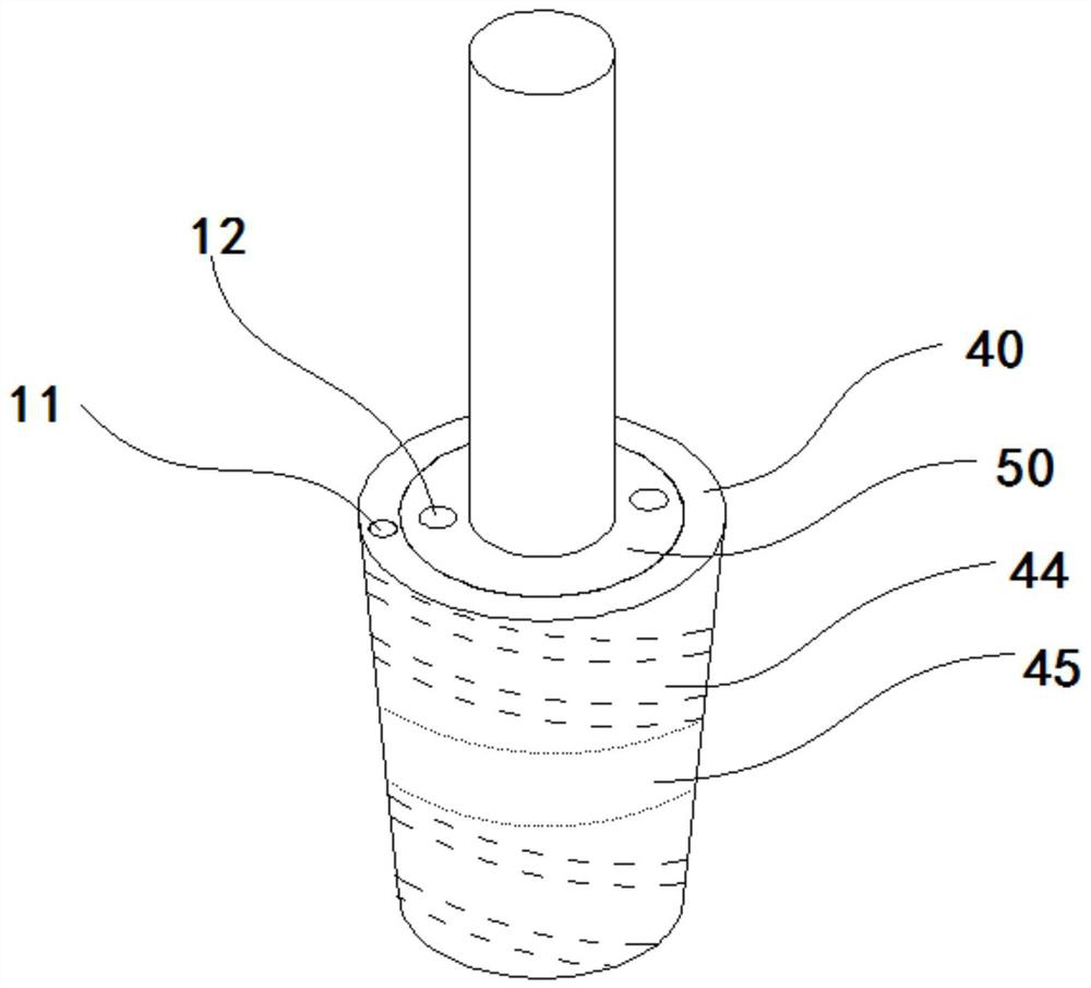
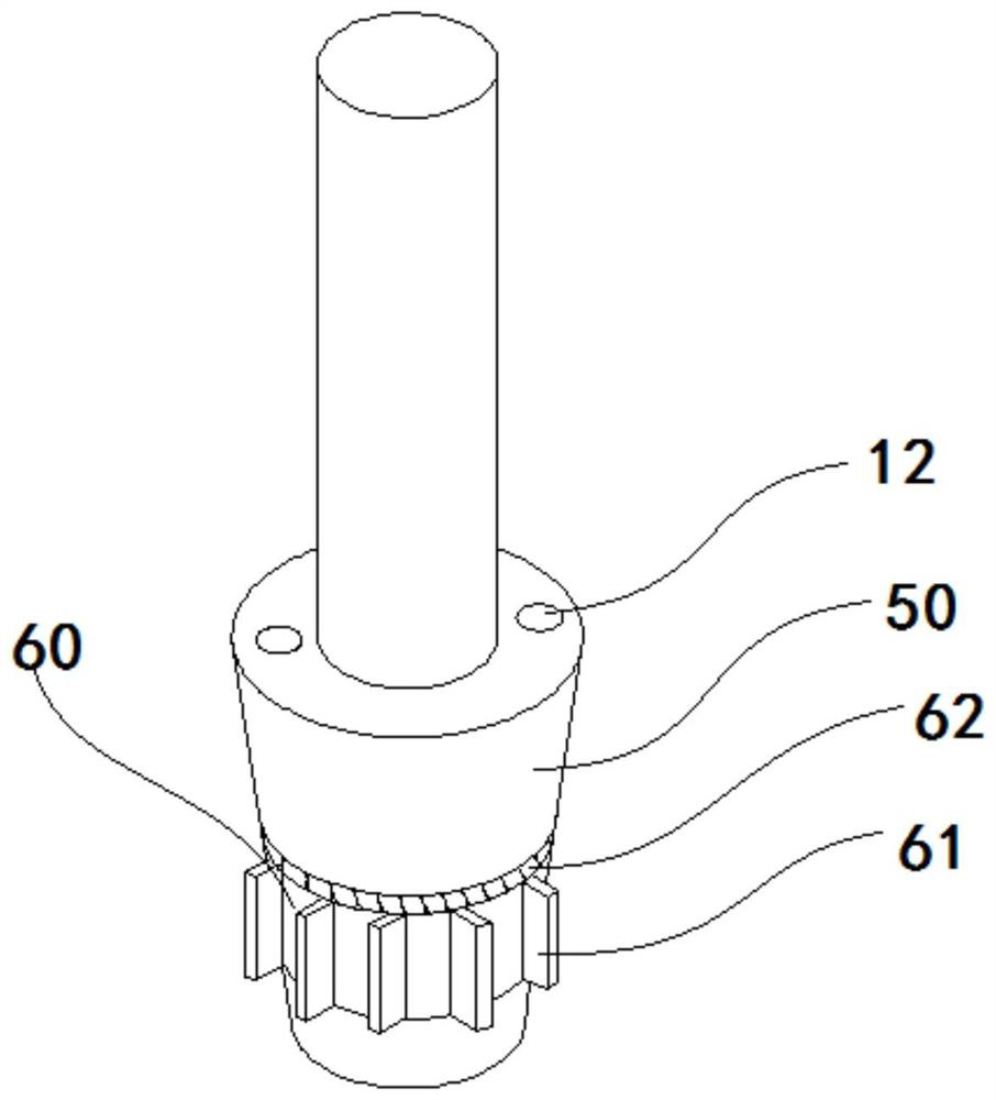
[0021] as attached figure 1 Shown, a kind of plasma powder surfacing device that alloy powder makes full use of, comprises, welding torch body 100; This welding torch body 100 comprises the front torch body 10 and rear torch body 20 of detachable fixed connection; Front torch body 10 and rear torch An insulator 30 is arranged between the bodies 20 and can be locked by a locking ring;

[0022] Between the front gun body 10 and the rear gun body 20, a circulating cooling water channel 13, a protective gas channel 11, an ion gas channel and a powder feeding channel 12 communicated with each other are provided; One hole, the second hole corresponding to the powder feeding channel 12, the third hole for circulating cooling water to pass through, and the central hole for ion gas to pass through; The plasma powder surfacing machine has a welding unit connected to the tungsten electrode of the welding gun body, a cooling water tank connected to the circulating cooling water channel 1...


PUM


Abstract

A plasma powder surfacing device that fully utilizes alloy powder is characterized in that it includes a welding torch body; the welding torch body includes a detachable and fixedly connected front torch body and a rear torch body; wherein, the front end of the front torch body is threadedly connected with a nozzle, and The front gun body is threadedly connected with a protective cover for covering the nozzle, and the distance between the protective cover and the nozzle forms a spiral protective gas channel; the rear gun body is provided with a protective gas inlet, which communicates with the spiral protective gas channel, and the protective cover The lower end is provided with a protective gas outlet; the rear gun body is provided with a powder inlet hole, and the powder inlet hole is connected to the powder feeding channel; it also includes a rotating powder feeding mechanism, which is connected to the powder feeding channel, and the rotating powder feeding mechanism is located in the spiral protective gas outlet. In the channel, it is driven by the protective gas to rotate, and when the rotary powder feeding mechanism rotates, the powder is discharged towards the arc column of the nozzle in the circumferential direction. The invention adopts the protection gas to drive the rotating powder feeding mechanism to rotate, so that the alloy powder is discharged in the circumferential direction, and the powder discharge is uniform to prevent blockage.

Description

Technical field: [0001] The invention relates to the field of plasma powder surfacing welding, in particular to a plasma powder surfacing device for fully utilizing alloy powder. Background technique: [0002] As a method of surface strengthening, powder plasma arc surfacing technology can improve the wear resistance and corrosion resistance of the surface of the part by cladding a layer of alloy powder with special properties on the surface of the part, thereby prolonging its service life. This technology has the advantages of high temperature, low dilution rate and good controllability, and is widely used in aerospace, ships, valves, mining machinery, screw and other industries. [0003] Because the plasma powder surfacing gun needs to melt the metal powder, the metal powder is mostly fed through the powder feeding channels distributed on both sides. The powder feeding holes connected with the powder feeding channels are set on the welding torch, so the powder feeding hole...

Claims


Application Information

Patent Timeline
Patent Type & Authority Patents(China)
IPC IPC(8): B23K10/02
CPCB23K10/027
Inventor 郭风忠杨晓燕周银周梦醒张军保王文红闵辉牛军李新强
Owner NINGXIA WUZHONG HAOYUN WELDER
Features
  • R&D
  • Intellectual Property
  • Life Sciences
  • Materials
  • Tech Scout
  • Unparalleled Data Quality
  • Higher Quality Content
  • 60% Fewer Hallucinations
Learn More