Hole exploring method for flow drilling tightening equipment

A kind of equipment, flow drilling technology, applied in the direction of metal processing equipment, measuring/indicating equipment, metal processing machinery parts, etc., can solve the problems that riveting equipment cannot be automatically adapted, increase production time and cost, and accuracy cannot be guaranteed, etc., to achieve Eliminate hole depth measurement errors, reduce labor costs, and minimize ambient light interference

Active Publication Date: 2019-12-20
ANHUI JEE AUTOMATION EQUIP CO LTD
View PDF10 Cites 0 Cited by
  • Summary
  • Abstract
  • Description
  • Claims
  • Application Information

AI Technical Summary

Problems solved by technology

[0005] 1. The alignment process of the rivet 4 and the pre-drilled hole has a low degree of automation, a large workload of manual intervention, and a long debugging time;
[0006] 2. Since each riveting point needs to be searched through the above operations, the production time and cost are greatly increased;
[0007] 3. When using a caliper to manually measure the hole depth, there is no downforce between the upper plate and the lower plate, but in the actual riveting, the riveting equipment has a downforce on the plate. This difference makes the obtained through manual measurement. There is an error between the hole depth parameter and the actual hole depth in the riveting state, and the riveting equipment cannot automatically adapt to this error, and even cause the riveting process to stop; There is still an error in the value, so that the accuracy cannot be guaranteed, and there may be riveting failure problems

Method used


Image

  • Hole exploring method for flow drilling tightening equipment
  • Hole exploring method for flow drilling tightening equipment
  • Hole exploring method for flow drilling tightening equipment

Examples


Embodiment Construction

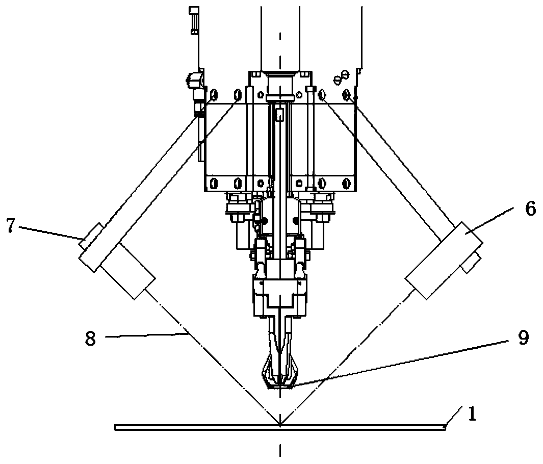
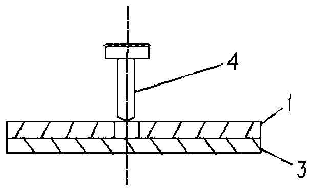
[0035] see figure 1 , figure 2 and image 3 , the present embodiment is a flow drilling and tightening equipment probing method, and its probing refers to the pre-opening in the upper layer plate 1 with pre-opening holes in the riveting parts when using the flow drilling and tightening equipment to rive the parts to be riveted. The position and depth of the hole are detected.

[0036] In the present embodiment, the drilling method of the flow drilling and tightening equipment is carried out as follows:

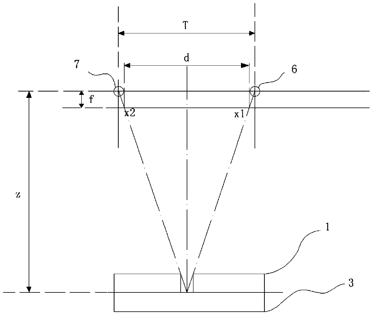
[0037] Step 1. Fixedly install the main camera 6 on the gun head side of the flow drill tightening equipment gun 2, and use the main camera 6 to take pictures to obtain photographed images of the relative positions of the flow drill tightening equipment gun 2 and the pre-opened holes in the upper plate 1 ; The captured image contains at least position information of reference points at three different positions, and the reference points are fixed points with known spatial ...


PUM


Abstract

The invention discloses a hole exploring method for flow drilling tightening equipment. The hole exploring method comprises the following steps of obtaining a shooting image of a relative position ofa flow drilling tightening equipment gun to a pre-drilled hole of an upper-layer plate by using a one-sided main camera, wherein the shooting image at least contains position information of referencepoints on three different positions; performing information processing to obtain predrilling boundary information in the shooting image, and further realizing hole site detection for predrilling; respectively shooting the same position of a lower-layer plate in the pre-drilled hole of the flow drilling tightening equipment at the pre-determined pressure by using cameras which are symmetrically arranged on two sides of a gun head to obtain a main camera image and an auxiliary camera image at the pre-determined pressure; and realizing the site detection for predrilling by calculating. Accordingto the method, automatic hole finding and hole depth measurement of the flow drilling tightening equipment can be realized under the control of a computer system, and thus successful riveting is ensured and the working efficiency is improved.

Description

technical field [0001] The invention relates to the field of body-in-white welding, and more specifically relates to a method for finding holes and measuring the depth of holes with flow drilling and tightening equipment. Background technique [0002] The flow drilling and tightening process is referred to as FDS, which is one of the commonly used processes for steel-aluminum hybrid body connection. Such as image 3 As shown, in the flow drilling and tightening FDS process, the equipment implements connection for two-layer boards or three-layer boards, image 3 The figure includes the upper plate 1 and the lower plate 3. According to the requirements of the flow drill tightening process, the upper plate 1 needs to be pre-drilled so that the upper plate 1 becomes the upper pre-opened plate to ensure the connection strength. and fatigue strength. There are strict requirements for the opening of the upper plate 1, including: the opening is circular, the diameter is 7.0-8.0 mm,...

Claims


Application Information

Patent Timeline
Patent Type & Authority Applications(China)
IPC IPC(8): B23Q17/24
CPCB23Q17/24
Inventor 刘蕾翁哲汤东华刘宏婕
Owner ANHUI JEE AUTOMATION EQUIP CO LTD
Why Eureka
Try Eureka