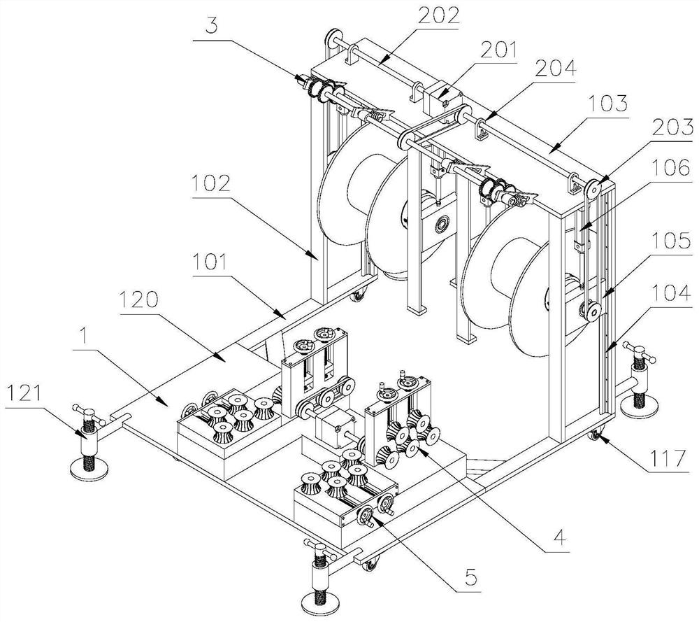
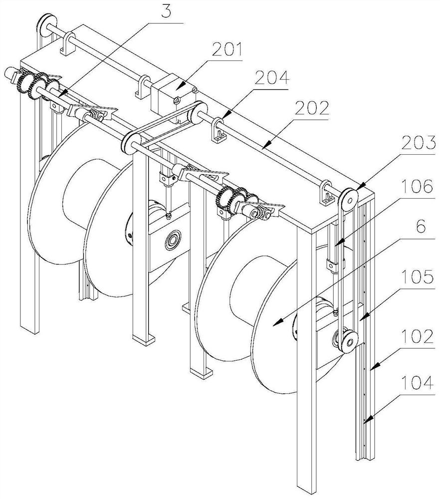
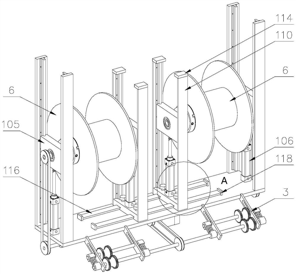
Multi-cable pay-off device for cable erection

A wire-paying device and cable technology, which is applied to the field of multi-cable wire-paying devices for cable erection, can solve the problems of time-consuming, labor-intensive, labor-intensive, heavy cable weight, etc., so as to avoid manual wire pulling, ensure the transmission effect, The effect of reducing labor intensity

Active Publication Date: 2021-04-13
JINAN CITY CHANGQING DISTRICT POWER SUPPLY CO OF STATE GRID SHANDONG ELECTRIC POWER CO +1
View PDF16 Cites 0 Cited by
  • Summary
  • Abstract
  • Description
  • Claims
  • Application Information

AI Technical Summary

Problems solved by technology

[0002] After the cable is produced, it is basically rolled on the reel, and then the reel (with the cable) is transported to the location that needs to be installed or replaced, and finally the cable on the reel is released by a special pay-off device. When using the traditional cable pay-off device, first lower the support slider of the pay-off device, then insert a steel pipe from one end of the slider into the reel, pass through the other end of the reel and place it on the On the support slider on the other side of the pay-off device, since the weight of the reel is as high as several tons, in order to effectively support the reel, a thicker steel pipe is often required, which not only makes the workers need a lot of physical strength when threading the pipe, but also wears the pipe. The efficiency of the tube is low, and the steel tube is simply placed on the pulley of the slider, and there is a hidden danger of falling off the pulley when the reel rotates, which is easy to cause a safety accident; Heavy weight, time-consuming and labor-intensive manual pulling, labor-intensive and low-efficiency

Method used


Image

  • Multi-cable pay-off device for cable erection
  • Multi-cable pay-off device for cable erection
  • Multi-cable pay-off device for cable erection

Examples


Embodiment Construction

[0040] Attached below Figure 1-11 , clearly and completely describe the technical solutions in the embodiments of the present invention, obviously, the described embodiments are only some of the embodiments of the present invention, not all of them. Based on the embodiments of the present invention, all other embodiments obtained by persons of ordinary skill in the art without making creative efforts belong to the protection scope of the present invention.

[0041] In describing the present invention, it should be understood that the terms "longitudinal", "transverse", "upper", "lower", "front", "rear", "left", "right", "vertical", The orientations or positional relationships indicated by "horizontal", "top", "bottom", "inner", "outer", etc. are based on the orientations or positional relationships shown in the drawings, and are only for the convenience of describing the present invention, rather than indicating or It should not be construed as limiting the invention by impl...


PUM


Abstract

The invention discloses a multi-cable pay-off device for cable erection. A first slide block is provided on one side of a column, first slide rails are provided at both ends of the first slide block, and clamping claws are provided on one side of the first slide block; One end of the first rotating shaft is provided with a first pulley; the second slider is provided with a gripper; the upper end of the first slider is connected with the top plate through the first oil cylinder, and the upper end of the second slider is connected with the third slider through the second oil cylinder; The driving device includes a first double-headed motor arranged on the top of the top plate, a second rotating shaft connected to both ends of the output shaft of the first double-headed motor, a second pulley installed on the second rotating shaft, and the second pulley is connected to the first double-headed motor through a belt. One wheel connection. In the present invention, claws are arranged at both ends of the vehicle frame, and the claws are used to support the reel, which prevents the reel from being separated from the pulley when it rotates, and ensures the stability of the reel, and a driving device is arranged on the top of the top plate, and the driving device is used to drive The reel rotates, which avoids manual wire pulling, reduces the labor load of workers, and improves the efficiency of unwinding.

Description

technical field [0001] The invention belongs to the technical field of electric power equipment, in particular to a multi-cable pay-off device for cable erection. Background technique [0002] After the cable is produced, it is basically rolled on the reel, and then the reel (with the cable) is transported to the location that needs to be installed or replaced, and finally the cable on the reel is released by a special pay-off device. When using the traditional cable pay-off device, first lower the support slider of the pay-off device, then insert a steel pipe from one end of the slider into the reel, pass through the other end of the reel and place it on the On the support slider on the other side of the pay-off device, since the weight of the reel is as high as several tons, in order to effectively support the reel, a thicker steel pipe is often required, which not only makes the workers need a lot of physical strength when threading the pipe, but also wears the pipe. The...

Claims


Application Information

Patent Timeline
Patent Type & Authority Patents(China)
IPC IPC(8): B65H49/32B65H49/30H02G1/06
CPCB65H49/30B65H49/32B65H2701/34H02G1/06
Inventor 郭映歧张传磊贾军刘宁吕广风张红卫赵延玲张华周丽潘震
Owner JINAN CITY CHANGQING DISTRICT POWER SUPPLY CO OF STATE GRID SHANDONG ELECTRIC POWER CO
Why Eureka
Try Eureka