Crane operation mechanism rail gnawing prevention device, crane operation mechanism rail gnawing prevention deviation rectification control system, and crane operation mechanism rail gnawing prevention deviation rectification control method

A technology of operating mechanism and control system, applied in the direction of traveling mechanism, transportation and packaging, load hanging components, etc., can solve the problems of not easy to replace the guide wheel, large impact force, sudden contact with the side of the rail, etc. Economic and safety benefits, the effect of reducing lateral frictional resistance and eliminating major safety hazards

Inactive Publication Date: 2019-12-20
温州市特种设备检测研究院
View PDF7 Cites 2 Cited by
  • Summary
  • Abstract
  • Description
  • Claims
  • Application Information

AI Technical Summary

Problems solved by technology

If the screws of the shaft end baffle are not fastened properly or the fastening screws are loosened due to the shock and vibration during the working process of the bridge crane, the screws fall off after a period of use, causing the guide wheels to fall off, which poses a safety hazard. Easy to replace guide wheels
[0008] (2) In the prior art, the rail gnawing phenomenon of the crane operating mechanism (cart or trolley) cannot be solved, and the side guide wheel assembly is not installed on the underside of the wheel rim, and the side guide wheel is used to withstand the side of the rail and there is no There is a small gap between the wheel rim of the crane and the side of the rail, which will cause wear between the wheel edge and the track during the operation of the wheel group, and the stability of the crane will be poor during operation, and the lateral frictional resistance of the crane cannot be reduced, so that the small wheels and The friction noise of the track is large, and the rail gnawing phenomenon between the inner side of the wheel rim and the rail cannot be avoided
However, when the crane has a large lateral force, many problems will arise. When the crane runs from the center line of the track to one side, the horizontal wheel does not touch the side of the rail (the design gap is generally 10mm), and the horizontal wheel set It cannot play a role. When the offset reaches 10mm, the horizontal wheel will suddenly contact the side of the rail. The horizontal wheel must prevent the inertial deflection of the crane, which will generate a large impact force at this time
This kind of impact force will cause serious harm to the crane structure, horizontal wheels, and tracks. Failures such as bearing damage of the horizontal wheel set and positioning plate falling off often occur, and in severe cases, major safety accidents such as wheel derailment may occur.
At the same time, the large impact force loosens or breaks the bolts of the rail pressure plate in a large area continuously, causing problems such as floating and shifting of some sections of the rail.

Method used


Image

  • Crane operation mechanism rail gnawing prevention device, crane operation mechanism rail gnawing prevention deviation rectification control system, and crane operation mechanism rail gnawing prevention deviation rectification control method
  • Crane operation mechanism rail gnawing prevention device, crane operation mechanism rail gnawing prevention deviation rectification control system, and crane operation mechanism rail gnawing prevention deviation rectification control method
  • Crane operation mechanism rail gnawing prevention device, crane operation mechanism rail gnawing prevention deviation rectification control system, and crane operation mechanism rail gnawing prevention deviation rectification control method

Examples


Embodiment Construction

[0051] In order to make the object, technical solution and advantages of the present invention more clear, the present invention will be further described in detail below in conjunction with the examples. It should be understood that the specific embodiments described here are only used to explain the present invention, not to limit the present invention.

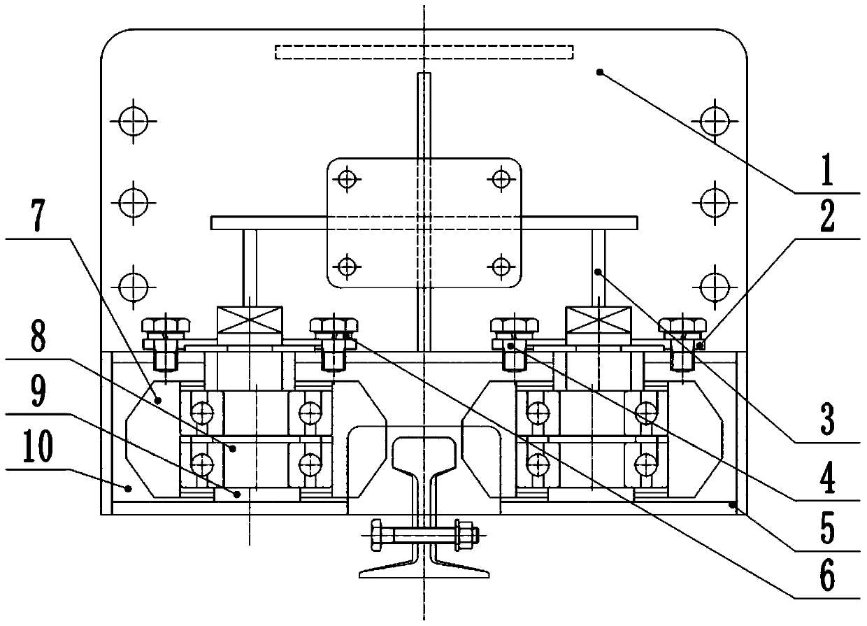
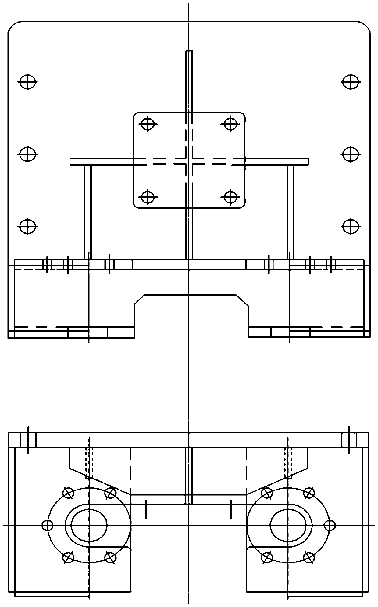
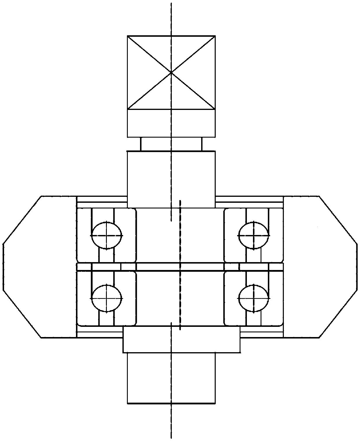
[0052] In the prior art, the rail gnawing phenomenon of the crane operating mechanism (cart or trolley) cannot be solved, without installing the side guide wheel assembly on the underside of the wheel rim, using the side guide wheel to withstand the side of the rail and not making the crane wheel There is a small gap between the wheel rim and the side of the rail, which causes wear between the wheel rim and the track during the operation of the wheel set. The stability of the crane is poor during operation, and the lateral frictional resistance of the crane cannot be reduced, so that the friction between the small wheel and ...


PUM


Abstract

The invention belongs to the technical field of cranes, and discloses a crane operation mechanism rail gnawing prevention device, a crane operation mechanism rail gnawing prevention deviation rectification control system, and a crane operation mechanism rail gnawing prevention deviation rectification control method. A plurality of first displacement sensors and a plurality of second displacement sensors are connected with a computer, the deflection angle of a crane frame relative to a rail is measured out by the displacement sensors, and then the deflection angle is converted into control voltage via proportional conversion through the computer; the control voltage is correspondingly added on first frequency converters and second frequency converters by a differential-action mode or a single-action mode, the first frequency converters and the second frequency converters are correspondingly connected with first control motors and second control motors, and the first control motors and the second control motors correspondingly adjust the stroke speed of a first driving wheel and the stroke speed of a second driving wheel. Rail gnawing between the inner side of a wheel flange of a wheel of an operation mechanism and the steel rail is effectively avoided, the stability of the crane in the operation process is enhanced, the operation side friction resistance of the crane is reduced,and friction noises between the wheel and the rail are reduced. Simultaneously, great potential safety hazards brought by the rail gnawing are eliminated, and safe operation of crane equipment and people safety are effectively ensured.

Description

technical field [0001] The invention belongs to the technical field of cranes, and in particular relates to an anti-gnawing rail device for a crane operating mechanism, a deviation correction control system and a method. Background technique [0002] Currently, the closest prior art: [0003] With the continuous development of the manufacturing industry, automated production lines are more and more widely used. However, in the process of product production in automated production lines, there are some horizontal or vertical lifting and handling within a certain range in material handling, process flow, and quality inspection. As a key process equipment or important auxiliary equipment machinery to reduce heavy labor, improve work efficiency, and realize production, cranes have been widely used in our lives. Cranes are special equipment. They are mostly used in workshops, warehouses or stockyards for lifting and lifting materials. Because they can replace a lot of manual lab...

Claims


Application Information

Patent Timeline
Patent Type & Authority Applications(China)
IPC IPC(8): B66C9/16B66C13/16
CPCB66C9/16B66C13/16
Inventor 尤戈苏立鹏金樟民方学宠娄益凡吴安定李拥军易灿灿
Owner 温州市特种设备检测研究院
Why Eureka
Try Eureka