Process chamber and semiconductor device

A process chamber and chamber technology, applied in metal material coating process, ion implantation plating, coating, etc., can solve the uneven direction and speed of gas movement, reduce the ionization efficiency of process gas, and affect the thickness of deposited film Uniformity and other issues to achieve the effect of improving collision efficiency, improving process capability and product quality, and improving the composition of compound films

Active Publication Date: 2019-12-20
BEIJING NAURA MICROELECTRONICS EQUIP CO LTD
View PDF9 Cites 10 Cited by
  • Summary
  • Abstract
  • Description
  • Claims
  • Application Information

AI Technical Summary

Problems solved by technology

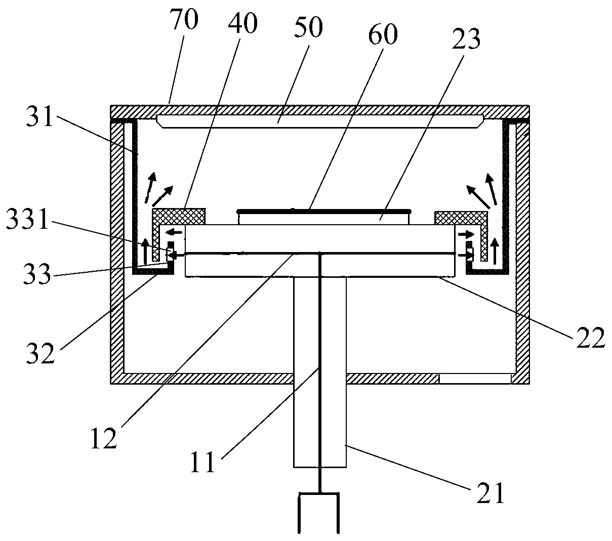
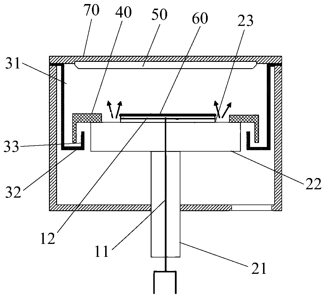
[0003] In the film-forming process chamber of existing PVD equipment, its air inlet is generally located on one side of the chamber, near the bottom, and the air inlet of the cold pump is located on the other side of the chamber bottom, so that the base is close to the air inlet and the air outlet. The gas flows in different directions on both sides, resulting in uneven direction and rate of gas movement in the process area above the susceptor, thus affecting the uniformity of the deposited film thickness
In addition, limited by the current chamber structure and air intake method, when the process gas enters the process area, most of it is directly pumped away by the cold pump, which not only reduces the ionization efficiency of the process gas, but also may affect the sputtering start ( When there is an insulating gas between the two electrodes, the start-up moment when the gas between the electrodes is broken down and emits light can be called ignition) and the stability of the process

Method used


Image

  • Process chamber and semiconductor device
  • Process chamber and semiconductor device
  • Process chamber and semiconductor device

Examples


Embodiment Construction

[0029] The present application is described in detail below, and examples of embodiments of the present application are shown in the drawings, wherein the same or similar reference numerals denote the same or similar components or components having the same or similar functions throughout. Also, detailed descriptions of known technologies will be omitted if they are not necessary to illustrate the features of the present application. The embodiments described below by referring to the figures are exemplary only for explaining the present application, and are not construed as limiting the present application.

[0030] Those skilled in the art can understand that, unless otherwise defined, all terms (including technical terms and scientific terms) used herein have the same meanings as commonly understood by those of ordinary skill in the art to which this application belongs. It should also be understood that terms, such as those defined in commonly used dictionaries, should be ...


PUM


Abstract

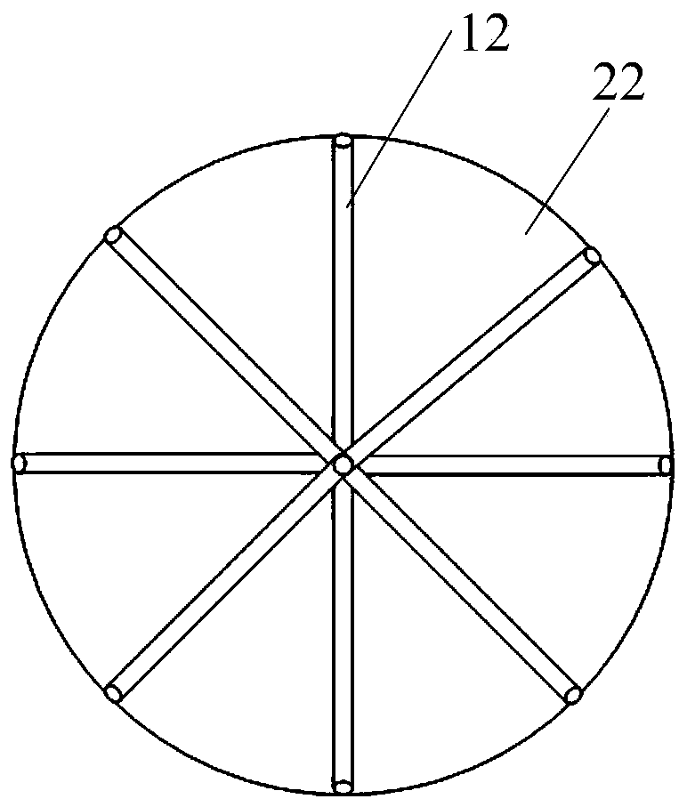
The invention provides a process chamber and a semiconductor device. The process chamber involves a chamber body and a base and an air inlet pipeline arranged in the chamber body, wherein the air inlet pipeline comprises a main air inlet channel and a plurality of diversion channels, the plurality of diversion channels are arranged in the base and are correspondingly in communication with the mainair inlet channel, and an air outlet of each diversion channel is located on the outer peripheral surface of the base. By applying the process chamber, the influence of the offset extraction of a cold pump on the uniformity of a deposited film can be effectively weakened, the gas movement of the process area is more uniform, the uniformity of the deposited film is improved, and the process capability and the product quality of the device are improved.

Description

technical field [0001] The present invention relates to the technical field of semiconductors, in particular to a process chamber and semiconductor equipment. Background technique [0002] With the continuous development of semiconductor technology, the requirements for film thickness uniformity on the surface of the wafer during the process are becoming more and more stringent. For example, in some optical fields, the thickness uniformity of ITO (indium tin oxide) It is required that its fluctuation range does not exceed a few angstroms (A), which requires PVD (Physical Vapor Deposition, physical vapor deposition) equipment to have more precise and controllable process capabilities. [0003] In the film-forming process chamber of existing PVD equipment, its air inlet is generally located on one side of the chamber, near the bottom, and the air inlet of the cold pump is located on the other side of the chamber bottom, so that the base is close to the air inlet and the air ou...

Claims


Application Information

Patent Timeline
Patent Type & Authority Applications(China)
IPC IPC(8): C23C14/56C23C14/34H01J37/34
CPCC23C14/34C23C14/56H01J37/3411
Inventor 赵联波王宽冒郑金果郭浩王涛
Owner BEIJING NAURA MICROELECTRONICS EQUIP CO LTD
Why Eureka
Try Eureka