Plant non-isolated state vacuumizing device and use method thereof

A vacuum device, non-isolated technology, which is applied in the field of genetic modification, can solve the problems that the operation cannot be completed in the laboratory vacuum box due to its large size, and the vacuum operation of plants cannot be realized, so as to achieve the effect of improving the efficiency of genetic modification

Inactive Publication Date: 2019-12-20
SHANGHAI ACAD OF AGRI SCI
View PDF7 Cites 0 Cited by
  • Summary
  • Abstract
  • Description
  • Claims
  • Application Information

AI Technical Summary

Problems solved by technology

[0002] Plant transgenic technology has been widely used in scientific research and breeding. At present, the most widely used is Agrobacterium-mediated transgenic technology. Most plant tissues are difficult to infiltrate Agrobacterium, and vacuum assistance is required during the infection process. Herbs are due to The plant is small, the tissue is tender, and it can be potted. It can be vacuumed by inverting the plant and dipping it into the Agrobacterium solution in the laboratory vacuum box to complete the infection process. Due to the tall plants, woody plants cannot be vacuumed in a non-isolated state. For example, plants such as pears, loquats, and blueberries cannot be operated in a laboratory vacuum box due to their large size, and need to be vacuumed in a non-isolated state, and there is currently no corresponding device
[0003] The patent application publication No. CN202460248U discloses a vacuum filtration device, which includes a melting vessel, a funnel arranged on the melting vessel, a vacuum filtering tube with one end installed on the suction filter of the melting vessel, and a vacuum compression pump. The funnel is provided with a filter layer, and the other end of the vacuum filter pipe is equipped with a connecting pipe device, which communicates with the vacuum compression pump through the vacuum suction filter steel pipe, and is arranged between the connecting pipe device and the vacuum compression pump. There is a pressure control device, and a heat dissipation fan is arranged on one side of the vacuum compression pump; although this device can perform vacuuming operations, it cannot realize the vacuuming operation of plants in a non-isolated state. For this reason, we now provide A plant vacuum device in a non-isolated state and its use method to solve the above technical problems

Method used


Image

  • Plant non-isolated state vacuumizing device and use method thereof

Examples


Embodiment 1

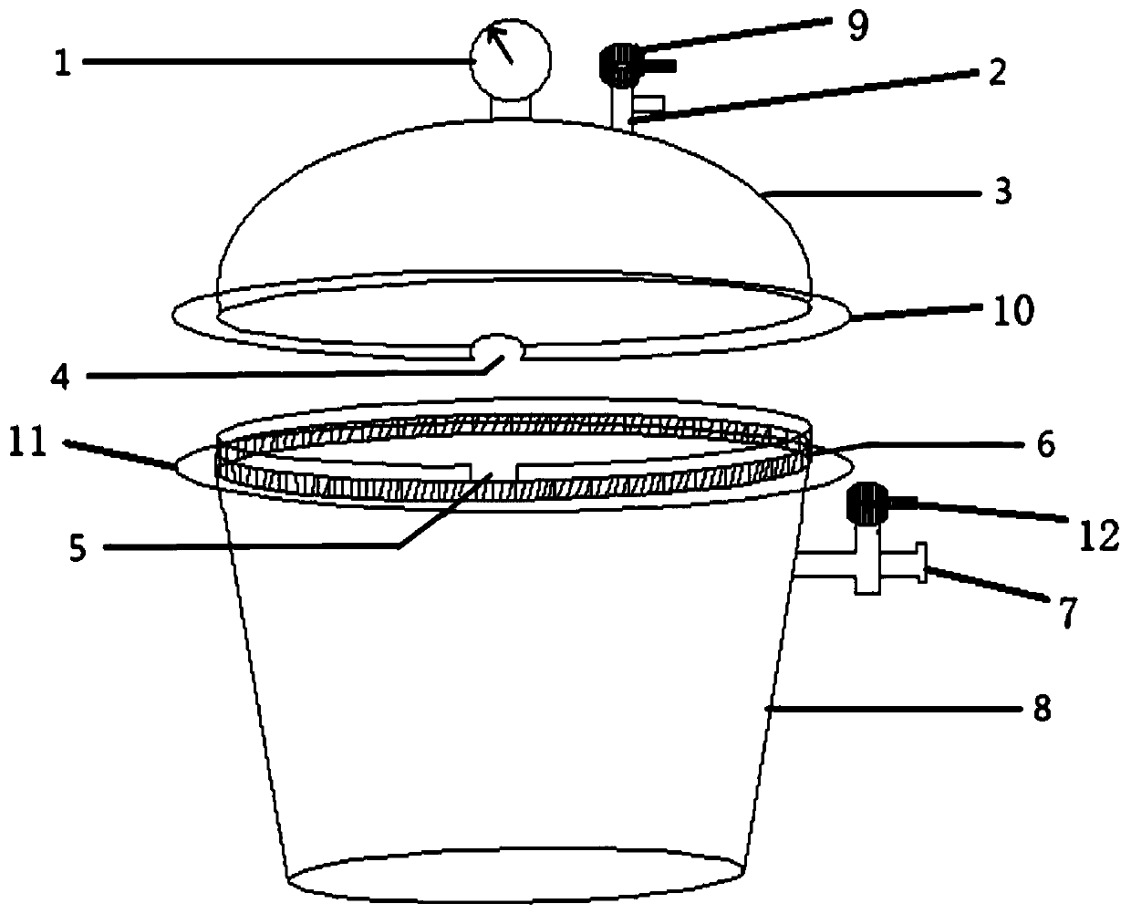
[0023] see figure 1 , a vacuum device for plants in a non-isolated state, comprising a barrel body 8, the upper end of the barrel body 8 is connected with an upper cover 3 matched with the barrel body 8 through a sealing mechanism, and an upper bayonet 4 is provided on the upper edge of the barrel body 8, and the upper end of the barrel body 8 3 The lower edge is provided with a lower bayonet 5 vertically corresponding to the upper bayonet 4 .

[0024] An air inlet pipe 7 is installed on the barrel body 8, and a valve II12 is installed on the air inlet pipe 7. The air inlet pipe 7 is used to connect with an external vacuum pump to vacuumize the inside of the device. A valve I9 ​​is ​​installed, and a pressure gauge 1 is installed on the top of the upper cover 3 . The provided pressure gauge 1 is used to observe the air pressure value inside the device in time to achieve a vacuum environment.

[0025] Specifically, when vacuumizing the plant in a non-isolated state, the upper...

Embodiment 2

[0032] On the basis of Embodiment 1, in addition, the upper bayonet 4 and the lower bayonet 5 are semicircular structures, and the semicircular structure makes the upper bayonet 4 and the lower bayonet 5 can be closely connected with the branches or flower stems of woody plants. Good fitting effect, can better accommodate and clamp woody plants, and is easy to operate.

[0033] Further, the sealing mechanism in this device includes an annular web I10 sleeved and fixed on the lower edge of the upper cover 3 and an annular web II11 sleeved and fixed on the upper edge of the barrel body 8 and opposite to the annular web I10. 8. The upper fitting sleeve is provided with a sealing ring 6 on the annular spoke plate II11.

[0034] When the upper cover 3 and the barrel body 8 are mated and connected, the annular web I10 and the annular web II11 are relatively close, and the sealing ring 6 located between them is pressed tightly, and the upper and lower edges of the sealing ring 6 can ...


PUM


Abstract

The invention discloses a plant non-isolated state vacuumizing device, and relates to the technical field of transgenosis. The plant non-isolated state vacuumizing device comprises a barrel body, wherein the upper end of the barrel body is connected with an upper cover through a sealing mechanism, the upper cover is matched with the barrel body, the upper edge of the barrel body is provided with an upper bayonet, and the lower edge of the upper cover is provided with a lower bayonet vertically corresponding to the upper bayonet. A use method of the plant non-isolated state vacuumizing device comprises the steps of 1, placing a tissue to be genetically modified of a non-isolated plant in the barrel body; and 2, covering the upper cover to form a closed space with the barrel body, wherein the upper bayonet and the lower bayonet are used for allowing the tissue to be genetically modified to pass through. According to the plant non-isolated state vacuumizing device, the defect that vacuumizing can not be carried out caused by wood plant agrobacterium infection is overcome, branches or flower stalks of the wood plant are placed into an open vacuum container, gaps between the upper bayonet and the lower bayonet and the plant are sealed by using semi-flowable flexible glue, vacuumizing is carried out by a vacuum pump, vacuumizing of the plant tissue in a non-isolated state is realized, and agrobacterium-mediated transgenic efficiency can be remarkably improved.

Description

technical field [0001] The invention relates to the field of transgenic technology, in particular to a plant vacuum device in a non-isolated state and a method for using the same. Background technique [0002] Plant transgenic technology has been widely used in scientific research and breeding. At present, the most widely used is Agrobacterium-mediated transgenic technology. Most plant tissues are difficult to infiltrate Agrobacterium, and vacuum assistance is required during the infection process. Herbs are due to The plant is small, the tissue is tender, and it can be potted. It can be vacuumed by inverting the plant and dipping it into the Agrobacterium solution in the laboratory vacuum box to complete the infection process. Due to the tall plants, woody plants cannot be vacuumed in a non-isolated state. For example, plants such as pears, loquats, and blueberries cannot be operated in a laboratory vacuum box due to their large size, and need to be vacuumed in a non-isolat...

Claims


Application Information

Patent Timeline
IPC IPC(8): F04B37/14F04B39/00F04B39/10
CPCF04B37/14F04B39/00F04B39/10
Inventor 蒋爽骆军张学英安海山王晓庆徐芳杰
Owner SHANGHAI ACAD OF AGRI SCI
Why Eureka
Try Eureka