
Efficient energy-saving self-priming pump

A high-efficiency, energy-saving, self-priming pump technology, applied to pumps, driving pumps, pump devices, etc., can solve the problems that self-priming pumps do not have self-priming function, cannot be used in water, and the motor cannot be cooled, so as to achieve working application Wide range, small footprint, good heat dissipation effect

Inactive Publication Date: 2019-12-20
河北汇通泵业有限公司
View PDF10 Cites 1 Cited by
  • Summary
  • Abstract
  • Description
  • Claims
  • Application Information

AI Technical Summary

Problems solved by technology

[0003] The traditional self-priming pump studio uses the motor shaft to drive the impeller inside the volute to rotate at high speed to realize the pumping work. Generally, self-priming pumps do not have self-priming function and cannot be put into water.
[0004] The working chamber of the traditional self-priming pump drives the fan at the tail end to rotate at high speed through the motor shaft, generating counter-airflow to dissipate heat from the motor casing. There is no heat dissipation inside the motor, and there is a certain resistance to the high-speed rotation of the fan, resulting in high power loss.

Method used


Image

  • Efficient energy-saving self-priming pump
  • Efficient energy-saving self-priming pump
  • Efficient energy-saving self-priming pump

Examples


specific Embodiment approach 1

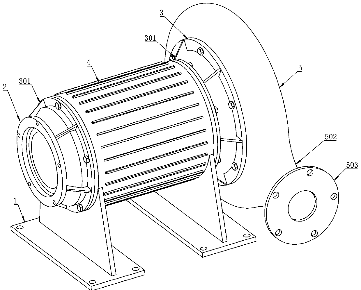
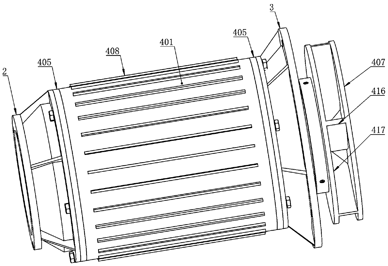
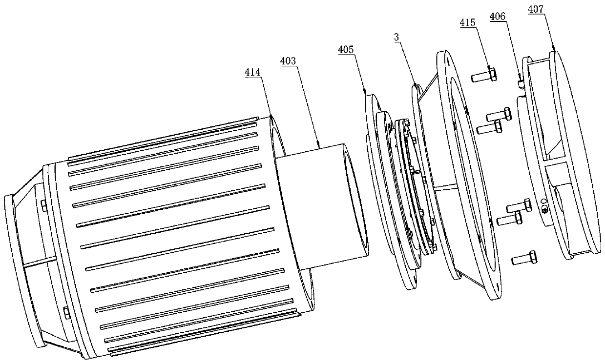
[0033] Specific implementation mode one: combine Figure 1-9As shown, a high-efficiency energy-saving self-priming pump is characterized in that it includes a base 1, an inlet flange 2, a connecting flange 3, a hollow drive motor device 4 and a volute 5; the hollow drive motor device 4 is fixed on the base 1 top; the inlet flange 2 is fixedly arranged on the left end of the hollow drive motor device 4; the volute 5 is fixedly arranged on the right end of the hollow drive motor device 4 through the connecting flange 3; the inlet flange 2 and the outer periphery of the connecting flange 3 A plurality of reinforcing ribs 301 are provided; the hollow drive motor device 4 includes a motor housing 401, a stator 402, a main shaft 403, a retaining spring 404, a mechanical seal assembly 405, a set screw 406 and a turntable 407; the motor A number of heat dissipation fins 408 are distributed on the outer periphery of the shell 401; the stator 402 is fixedly arranged in the middle positi...


PUM


Abstract

The invention relates to the technical field of self-priming pumps, in particular to an efficient energy-saving self-priming pump. According to the efficient energy-saving self-priming pump, the design of a hollow driving motor device is adopted, under the action of centrifugal blades, external water enters a volute through a water inlet in the middle of a main shaft, and heat generated during working of a rotor and a stator is absorbed by water at the water inlet position in the middle of the main shaft, so that the heat dissipation effect inside the motor is achieved, and the problems that atraditional motor dissipates heat through the tail end fan to the motor shell, heat dissipation is not available in the motor, a certain resistance exists in high-speed rotation of the fan, and the electric loss is high are solved; the two ends of the main shaft and the motor shell are sealed through mechanical sealing, the stator and the rotor can be sealed in the motor shell, a water pump can be directly put into water for pumping work, and the working application range is wide. According to the self-priming pump, heat dissipation can be conducted through the motor shell, heat dissipation can be conducted through the internal water flow, internal and external double heat dissipation is achieved, and the heat dissipation effect is good.

Description

technical field [0001] The invention relates to the technical field of self-priming pumps, in particular to a high-efficiency and energy-saving self-priming pump. Background technique [0002] The self-priming pump is a self-priming centrifugal pump, which has the advantages of compact structure, convenient operation, stable operation, easy maintenance, high efficiency, long life, and strong self-priming ability. There is no need to install a bottom valve in the pipeline, and it is only necessary to ensure that there is a quantitative suction liquid stored in the pump body before work. Different liquids can use different material self-priming pumps. [0003] The traditional self-priming pump studio uses the motor shaft to drive the impeller inside the volute to rotate at high speed to achieve pumping work. Generally, self-priming pumps do not have self-priming function and cannot be used in water. [0004] The working chamber of the traditional self-priming pump drives the...

Claims


Application Information

Patent Timeline
Patent Type & Authority Applications(China)
IPC IPC(8): F04D13/06F04D29/58F04D29/043H02K5/18H02K5/10H02K5/124F04D9/02F04D29/42
CPCF04D9/02F04D13/0646F04D29/043F04D29/426F04D29/4273F04D29/5806F04D29/586H02K5/10H02K5/124H02K5/18
Inventor 徐浩
Owner 河北汇通泵业有限公司
Learn More