Vacuum sintering furnace

A vacuum sintering furnace and vacuum technology, applied in furnaces, charge, muffle furnaces, etc., to improve the sintering quality, improve the sintering effect, and ensure the effect of temperature control

Inactive Publication Date: 2019-12-20
陈美香
View PDF6 Cites 1 Cited by
  • Summary
  • Abstract
  • Description
  • Claims
  • Application Information

AI Technical Summary

Problems solved by technology

[0004] The purpose of the present invention is to solve the above-mentioned problems of the existing vacuum sintering furnace, to provide a method to ensure the stability of the material during the sintering process through the upper pressing device and the lower supporting device, and to further effectively vacuumize through the vacuum device to prevent accidents Explosion, a vacuum sintering furnace that improves the temperature control effect through the furnace body, increases the service life, improves the sintering efficiency and improves the sintering quality

Method used


Image

  • Vacuum sintering furnace
  • Vacuum sintering furnace
  • Vacuum sintering furnace

Examples


Embodiment Construction

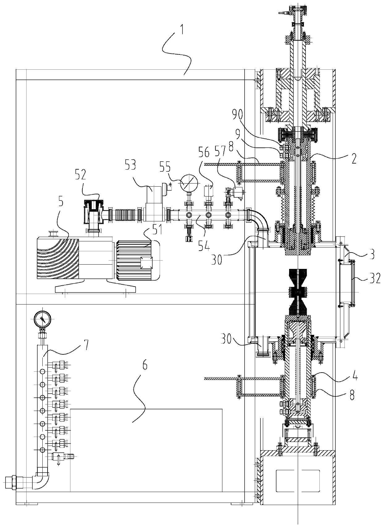
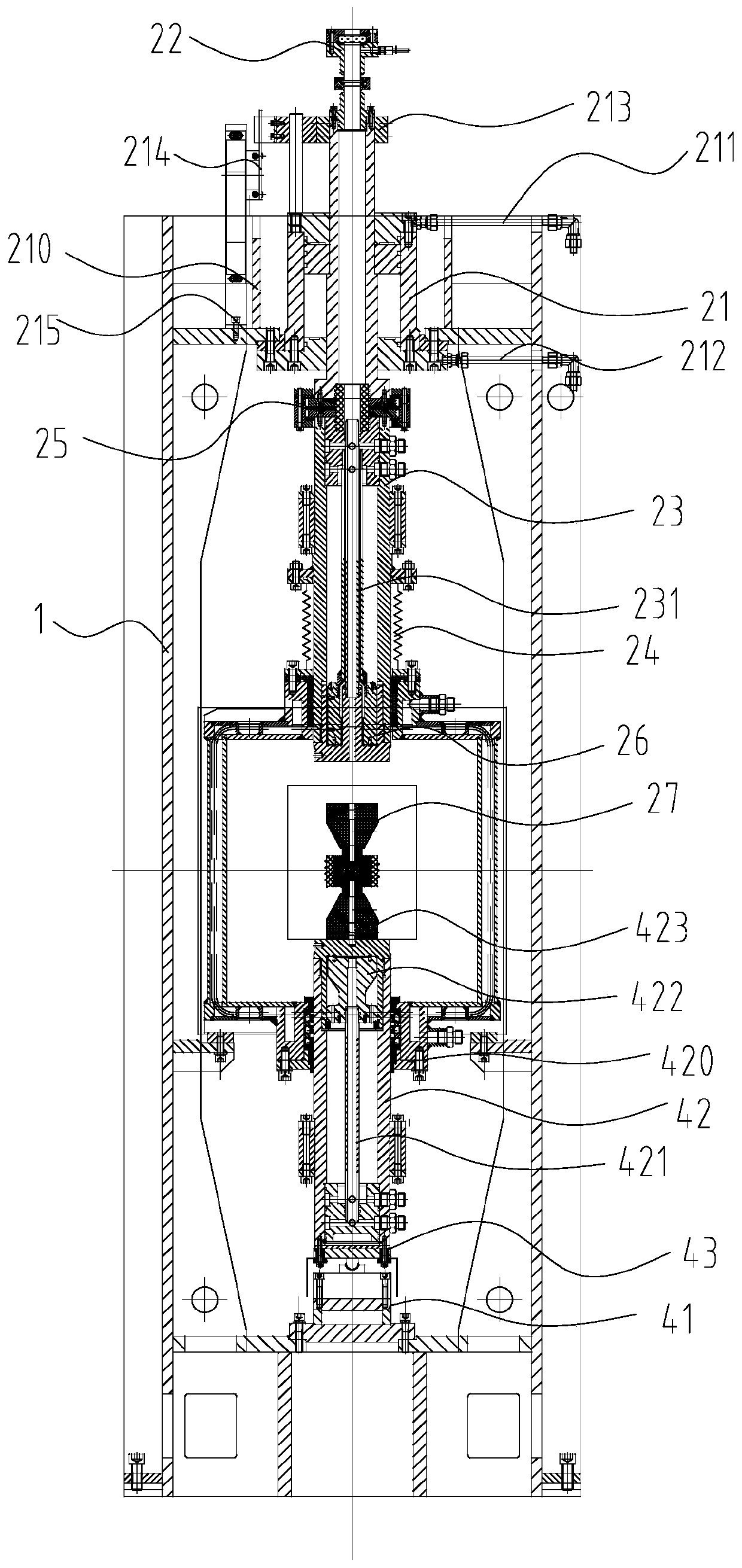
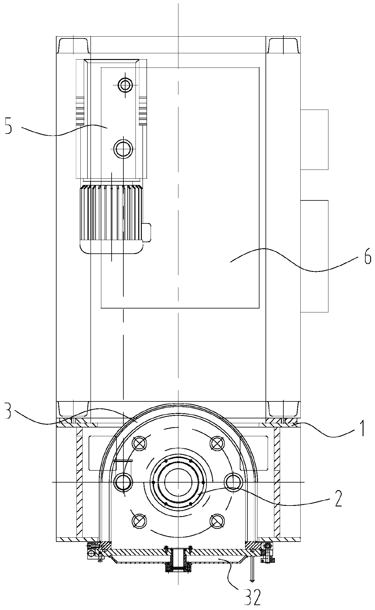
[0020] Such as figure 1 As shown, a vacuum sintering furnace includes a frame 1, an upper pressing device 2, a furnace body 3, a lower supporting device 4, a vacuum device 5, a hydraulic device 6, a water cooling device 7 and a control system; an upper pressing device 2, The furnace body 3 and the lower supporting device 4 are arranged on the front of the frame 1; the upper pressing device 2 is arranged on the top of the furnace body 3, and the upper pressing device 2 passes through the top of the furnace body 3 for compacting materials. The lower supporting device 4 is arranged at the bottom of the furnace body 3 ; the lower supporting device 4 passes through the bottom of the furnace body 3 for supporting materials and cooperates with the upper pressing device 2 . The vacuum device 5 is arranged on the rear portion of the frame 1, and the vacuum device 5 is connected with the furnace body 3; the hydraulic device 6 and the water cooling device 7 are respectively arranged on t...


PUM


Abstract

The invention relates to the technical field of ceramic vacuum sintering furnace. A vacuum sintering furnace comprises a rack, an upper part pressing device, a furnace body, a lower part supporting device, a vacuum device, a hydraulic device, a water cooling device; the upper part pressing device, the furnace body and the lower part supporting device are arranged at the front part of the rack; theupper part pressing device is arranged at the top of the furnace body, and the upper part pressing device penetrates through the top of the furnace body and used for pressing materials; the lower part supporting device is arranged in the bottom of the furnace body, and the lower supporting device penetrates through the bottom of the furnace body for supporting materials and is matched with the upper part pressing device; the vacuum device is arranged at the rear part of the rack, and the vacuum device is communicated with the furnace body; the hydraulic device and the water cooling device arerespectively arranged at the lower side of the rear of the rack; and the hydraulic device is used for performing hydraulic control, and the water cooling device for cooling control. This patent has the advantage of improving the ceramic material in the sintering process, improve the stability of the vacuum pumping effect to prevent the occurrence of accidental explosion, temperature control effect is improved, and the sintering efficiency is improved.

Description

technical field [0001] The invention relates to the technical field of ceramic vacuum sintering furnaces. Background technique [0002] Vacuum sintering furnaces are widely used for sintering ceramic powders, ceramic ferrules and other zirconia ceramics. Existing sintering furnace structure, such as a magnetic steel vacuum tube type sintering furnace disclosed in the Chinese utility model patent whose publication number is CN202955965U and whose announcement date is 2013.05. The cavity of the sintering material has a heating mechanism in the sintering furnace tube. The heating mechanism sinters the material in the cavity. The sintering furnace tube is connected with an air extraction system. and the exhaust system are connected to the control box, and the control box regulates the heating and vacuuming process; the sintering furnace is connected with a feeding pipe at the entrance of the sintering furnace tube, and the material is transported into the sintering furnace tube...

Claims


Application Information

Patent Timeline
Patent Type & Authority Applications(China)
IPC IPC(8): F27B5/04F27B5/18F27B5/06
CPCF27B5/04F27B5/06F27B5/18F27B2005/062F27M2001/035F27M2003/04
Inventor 陈美香朱仁康王晟聪
Owner 陈美香
Why Eureka
Try Eureka