Power generation structure and energy collection device

A power generation unit and electrode technology, applied in the direction of friction generators, etc., can solve the problems of TENG output peak ratio, power loss, output peak ratio, etc., to achieve the effect of optimizing circuit connection mode, reducing energy loss, and reducing power loss

Active Publication Date: 2019-12-20
BEIJING INST OF NANOENERGY & NANOSYST
View PDF5 Cites 0 Cited by
  • Summary
  • Abstract
  • Description
  • Claims
  • Application Information

AI Technical Summary

Problems solved by technology

The effective current of the typical short pulse output of TENG is much lower than the peak value, and there is a disadvantage of high output peak ratio. Some studies have solved the problem of partial power loss by connecting all friction nanogenerator units in parallel and then outputting them through rectification. , but the TENG output peak ratio of this circuit connection is usually between 6-10, which is still very high
The TENG structure based on the rotation-sliding mode proposed in some studies effectively reduces the peak ratio, but the continuous friction between the electrode and the dielectric layer will generate a lot of heat, causing damage to the friction material, and the working life needs to be improved, which limits this structure. Working life and commercialization of TENG
[0004] Therefore, solving the shortcomings of power loss when paralleling TENG, high TENG output peak ratio, and short life of the rotating structure at the same time is a technical problem that TENG needs to solve urgently as a supplement to distributed energy.

Method used


Image

  • Power generation structure and energy collection device
  • Power generation structure and energy collection device
  • Power generation structure and energy collection device

Examples


no. 1 example

[0079] In a first exemplary embodiment of the present disclosure, a power generating structure is provided, which is a rotary structure.

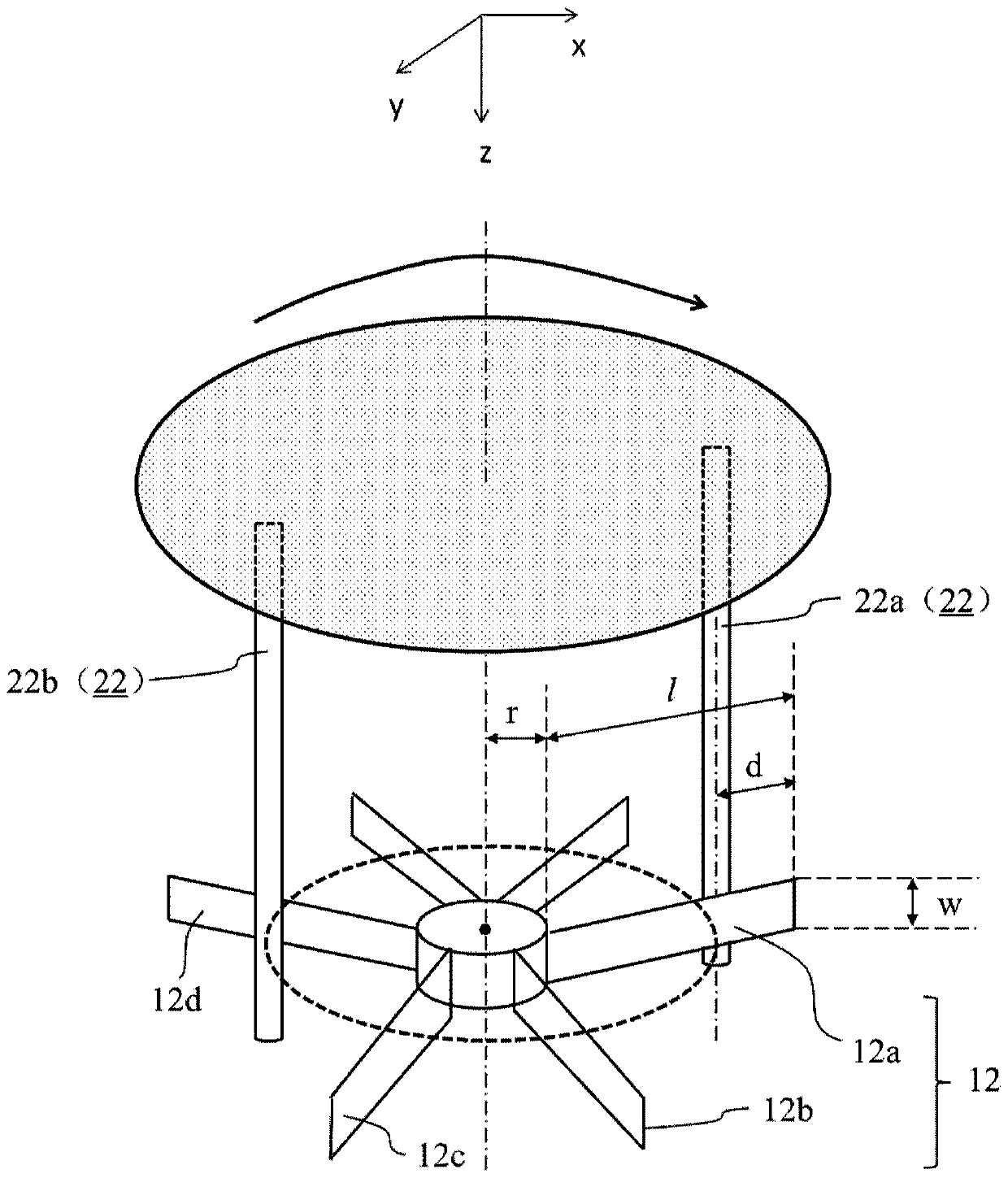
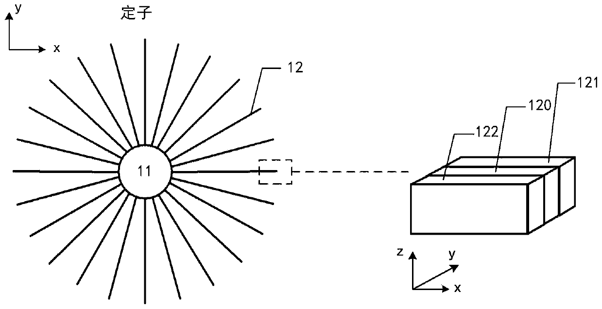
[0080] figure 1 It is a schematic diagram showing that the power generating structure is a rotating structure according to an embodiment of the present disclosure. figure 2 For such figure 1 The structure schematic diagram of the electrode unit group in the rotary structure shown as a stator, wherein the dotted line box shows a three-dimensional perspective view of one of the electrode units. Figure 4 For such figure 1 The schematic diagram of the structure in which the push rod in the rotary structure is shown as the rotor.

[0081] refer to figure 1 , figure 2 with Figure 4 As shown, the power generation structure of the present disclosure includes: an electrode unit group, including a plurality of electrode units 12 arranged at intervals, and the materials on the opposite surfaces of adjacent electrode units 12 are located in d...

no. 2 example

[0109] In the second exemplary embodiment of the present disclosure, a power generation structure is provided. On the basis of the structure of the first embodiment, the power generation structure of this embodiment optimizes the circuit connection mode and realizes low peak ratio and reduce power loss.

[0110] Image 6 It is a schematic diagram of a power generation structure including a plurality of uniformly distributed electrode units according to an embodiment of the present disclosure. Figure 7 with Figure 8 The comparison shows that Image 6 The power generation structure shown is a schematic diagram of using different circuit connection methods for electrical output. Figure 7 For such Image 6 In the power generation structure shown, each pair of electrode units is connected in parallel and rectified by a common rectifier bridge (single rectifier bridge). Figure 8 For such Image 6 In the power generation structure shown, each pair of electrode units is rect...

example 1

[0119] By adjusting the width of the electrode sheet, a higher equivalent current output can be obtained.

[0120] Figure 12 It is the output variation curve caused by different electrode width w in the power generation structure shown according to an example of the present disclosure. Here the radius of the support ring (first support) of the stator is 4cm, the number of electrode sheets (electrode units) is 24, the length of the electrode sheet is 10cm, the number of push rods is 4, and the push rod reaches the end of the electrode sheet The vertical distance is 2cm, and the width (w) of the electrode sheet ranges from 2cm to 5cm. Such as Figure 12 As shown, the peak ratio obtained in the test is between 1-2, and the equivalent current increases with the increase of the electrode width. At the same time, with the increase of the rotational speed, the equivalent current also gradually increases.


PUM

PropertyMeasurementUnit
Lengthaaaaaaaaaa
Lengthaaaaaaaaaa
Lengthaaaaaaaaaa

Abstract

The invention relates to a power generation structure and an energy collection device. The power generation structure comprises an electrode unit group and a pushing rod. The electrode unit group comprises a plurality of electrode units which are arranged at intervals, and materials on facing surfaces of adjacent electrode units are located in different triboelectric sequences. The pushing rod ispositioned at an interval of two adjacent electrode units or is close to a certain electrode unit. Under the action of external force, the pushing rod and the electrode unit group generate relative position movement, the path of the relative position movement is consistent with the distribution of the electrode unit group such that the pushing rod sequentially pushes and slides over the pluralityof electrode units in the electrode unit group, the electrode units which the pushing rod sequentially pushes and slides over and adjacent electrode units form a plurality of contact-separation type power generation units, and each power generation unit generates a plurality of electrical outputs with a sequential phase sequence according to the contact sequence with the pushing rod. The service life of the power generation structure is prolonged while the output performance is ensured, and the reliability is improved.

Description

technical field [0001] The disclosure belongs to the technical field of nanometer power generation, and relates to a power generation structure and an energy collection device. Background technique [0002] As a revolutionary technology for converting low-frequency mechanical energy into electrical energy, triboelectric nanogenerator (TENG) has aroused great interest of researchers due to its advantages of high peak power, light weight, simple design, environmental protection, and diverse material selection. These advantages make it a promising distributed energy supplementary technology to directly supplement the energy consumption of supercapacitors / batteries to drive small electronic devices. [0003] "Peak ratio" is defined as the ratio of the current peak value to the equivalent current. The effective current of the typical short pulse output of TENG is much lower than the peak value, and there is a disadvantage of high output peak ratio. Some studies have solved the p...

Claims


Application Information

Patent Timeline
IPC IPC(8): H02N1/04
CPCH02N1/04
Inventor 王杰李昕螈周灵琳其他发明人请求不公开姓名
Owner BEIJING INST OF NANOENERGY & NANOSYST
Why Eureka
Try Eureka