Multistage spinning roller

A spinning wheel and main spinning wheel technology, applied in the field of spinning, can solve problems such as curling, billet wrinkling, and affecting product quality, and achieve the effects of preventing vibration, wrinkling, and shaking

Pending Publication Date: 2019-12-24
浙江博翔旋压机床有限公司
View PDF2 Cites 0 Cited by
  • Summary
  • Abstract
  • Description
  • Claims
  • Application Information

AI Technical Summary

Problems solved by technology

[0005] But the rotary wheel has only one rotary wheel the same as other prior art. In the spinning process, after the flange of the rotary wheel is extruded to the blank, due to the contact process between the side edge of the rotary wheel and the blank, the spinning The rotation speed of the side edge of the wheel is different from that of the billet, which will easily cause the billet to wrinkle and curl, which will affect the quality of the product

Method used


Image

  • Multistage spinning roller
  • Multistage spinning roller
  • Multistage spinning roller

Examples


Embodiment 1

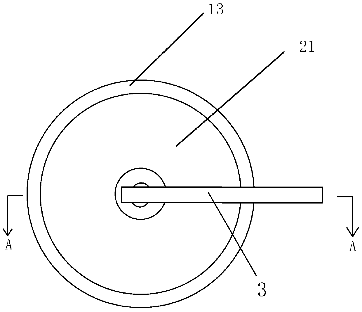
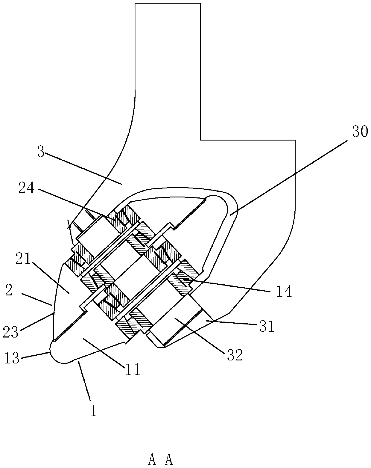
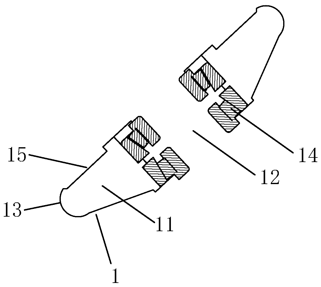
[0027] Embodiment 1: as Figure 1 to Figure 4 A multi-stage rotary wheel shown includes a main rotary wheel 1 and a rotary wheel frame 3 for installing the main rotary wheel 1, a notch 30 is set on the rotary wheel frame 3, and a notch 30 is provided at both ends of the notch 30 Fixed hole one 31, fixed shaft 32 is arranged on the fixed hole one 31, the fixed shaft 32 matches with the fixed hole one 31, the fixed shaft 32 is fixed in the fixed hole one 31, and is used for fixing the main roller 1 and the auxiliary roller 2 . The main wheel 1 includes a wheel body 11, and a flange 13 is arranged on the edge of the wheel body 11 in the circumferential direction. The material of the flange 13 is hard, which is beneficial to extruding the blank. In the middle of the wheel body one 11, a through hole one 12 through which the axial direction is penetrated is provided, and a bearing one 14 is arranged in the through hole one 12, and the bearing one 14 is fixed on the fixed shaft 32....

Embodiment 2

[0034] Example 2, such as Figure 5 , Image 6 As shown, other structures are basically the same as in Implementation 1. Due to the relatively large diameter of some billets, after spinning, due to the force of extrusion, the billet of the cylindrical body will be curled, and its curled surface exceeds the position of the auxiliary roller 2, so that the curled part of the billet will be Contact with other parts of the spinning machine will cause damage to other parts of the spinning machine, and also affect the quality of the blank. Therefore, in this embodiment, the notch 2 40 is set on the wheel frame 3, and the notch 2 40 and the The curled surface of the processed blank is opposite, and the two ends of the notch 40 are provided with a fixing hole 2 41, an auxiliary material shaft 42 is arranged on the fixing hole 2 41, an auxiliary material wheel 43 is arranged on the auxiliary material shaft 42, and an auxiliary material wheel 43 is set on the auxiliary material shaft 42...


PUM


Abstract

The invention discloses a multistage spinning roller, and belongs to the technical field of spinning. The multistage spinning roller comprises a main spinning roller (1) and a spinning wheel carrier (3). The main spinning roller (1) comprises a first roller body (11), and a first through hole (12) is formed in the middle of the first roller body (11). Auxiliary spinning rollers (2) are arranged onone side of the first roller body (11) and further comprise second roller bodies (21), and second through holes (22) are formed in the middles of the second roller bodies (21). The second through holes (22) and the first through hole (12) are located in the same axis. According to the multistage spinning roller, when the auxiliary spinning rollers (2) rotate passively, the surfaces of the auxiliary spinning rollers (2) and the surfaces of spun blanks can rotate at the same speed, friction is reduced, wrinkling and curling of the blanks are avoided, the adverse effects like blank vibrations can be prevented and product quality can be improved.

Description

technical field [0001] The invention belongs to the technical field of spinning, and in particular relates to a multi-stage rotary wheel composed of a main rotary wheel and a plurality of auxiliary rotary wheels. Background technique [0002] In the spinning process of the traditional spinning machine tool, the rotary wheel used is a single rotary wheel. The single rotary wheel is fixed on the fixed shaft through the bearing, and the blank is extruded through the flange of the rotary wheel to form the blank. . [0003] On October 26, 2011, the application date is October 26, 2011, and the application number is 201120413058.0. The Chinese utility model patent discloses a spinning wheel structure, including a wheel, the wheel is arranged on a pin shaft, and a wheel is arranged between the wheel disc and the pin shaft. There is a bearing, a flange is provided in the middle of the inner circumference of the wheel, the pair of bearings are respectively arranged on both sides of ...

Claims


Application Information

Patent Timeline
Patent Type & Authority Applications(China)
IPC IPC(8): B21D22/14
CPCB21D22/14
Inventor 徐唐健
Owner 浙江博翔旋压机床有限公司
Why Eureka
Try Eureka