
Cable-stayed bridge

A cable-stayed bridge and bridge body technology, which is applied to suspension bridges, bridges, bridge forms, etc., can solve the problems of inconvenient maintenance and repair, low load capacity of steel cable bridges, and unsuitable for vehicle traffic. The effect of stable bridge deck structure and reduction of construction costs

Inactive Publication Date: 2019-12-24
QINGDAO DUQIU NEW ENERGY TECH CO LTD
View PDF9 Cites 0 Cited by
  • Summary
  • Abstract
  • Description
  • Claims
  • Application Information

AI Technical Summary

Problems solved by technology

The steel cable bridge has the characteristics of low construction cost, fast speed and easy maintenance. However, the steel cable bridge has a small load capacity, and the bridge deck naturally droops into an arc with the steel cables, so it is not suitable for vehicle traffic.
[0003] At present, the large bridges that can facilitate the passage of vehicles are integrated as a whole, and the bridge body is supported by multiple piers. The construction cost is high, the construction period is long, and maintenance and repair are inconvenient

Method used


Image

  • Cable-stayed bridge
  • Cable-stayed bridge
  • Cable-stayed bridge

Examples


Embodiment 1

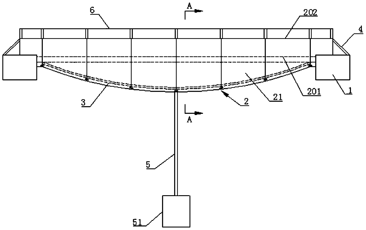
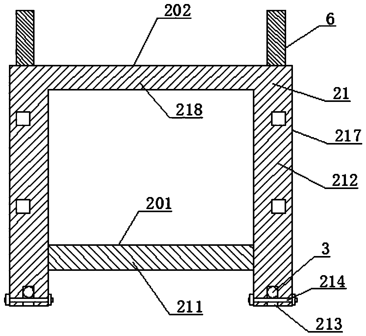
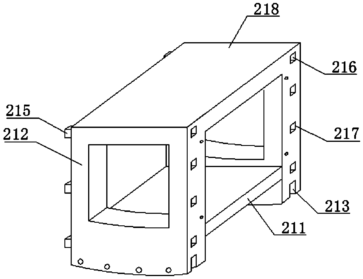
[0029] Such as Figure 1 to Figure 3 As shown, a cable-stayed bridge includes a bridge pier 1 and a bridge body 2 formed by splicing a plurality of bridge body splicing monomers 21. The bottom of the bridge body 2 is curved in an arc, and at least one passageway parallel to the horizontal plane is provided on the bridge body. The two ends of the bridge body 2 are fixed on the bridge pier 1, and steel cables 3 are installed between the bridge piers 1. The number of steel cables 3 is at least two, and the steel cables 3 pass through the bottom of the bridge body 2, and the bridge body splicing is single. Body 21 spans between two steel cables.

[0030] The bridge body splicing units 21 are fixedly connected by connectors, the bottom of the bridge body splicing units 21 adapts to the curvature of the bridge body, and the bridge body splicing units 21 are provided with a horizontal first passage board bordering the road surface 211 , the first passage plates 211 of the plurality ...

Embodiment 2

[0041] Such as Figure 4 As shown, compared with the first embodiment, the present embodiment has a plurality of piers 1 and bridge bodies 2, and is a large-scale cable-stayed bridge formed by butt joints of the cable-stayed bridges in the first embodiment.

[0042] The bridge body 2 is erected between two adjacent piers 1, and the structure and connection between the bridge piers 1 and the bridge body 2 are the same as those in the first embodiment.


PUM


Abstract

The invention relates to a cable-stayed bridge. The cable-stayed bridge comprises bridge piers and bridge body which is formed by splicing multiple bridge body splicing single bodies; a steel cable ismounted between the bridge piers; the bottom of the bridge body is arc and bent; at least one passing surface parallel to the horizontal plane is arranged on the bridge body; the two ends of the bridge body are fixed on the bridge piers; the bridge body splicing single bodies are fixedly connected with each other through connecting pieces; the radians of the bottoms of the bridge body splicing single bodies are adaptive to the bending radian of the bridge body; horizontal first passing plates bordering a pavement are arranged on the bridge body splicing single bodies; and the first passing plates of the multiple bridge body splicing single bodies are mutually spliced to form a first passing surface for vehicles to pass through. According to the cable-stayed bridge, a bridge deck providesthe passing surface to provide convenience for the passing of the vehicles, and therefore, the difficult problem that a traditional cable-stayed bridge is inconvenient for the vehicles to pass throughas the bridge deck of the traditional cable-stayed bridge is arc and the load capacity of the bridge deck of the traditional cable-stayed bridge is light is solved; by splicing the prefabricated bridge body splicing single bodies into the bridge body and using the steel cable to support the bridge body, a spliced and detachable bridge body structure is realized to facilitate construction and maintenance of the bridge body.

Description

technical field [0001] The invention relates to the technical field of bridge construction, in particular to a cable-stayed bridge. Background technique [0002] The cable-stayed bridge is a common bridge in the prior art, and the bridge deck is formed by laying plates on steel cables. The steel cable bridge has the characteristics of low construction cost, high speed and easy maintenance. However, the steel cable bridge has a small load capacity, and the bridge deck naturally droops into an arc with the steel cables, so it is not suitable for vehicle traffic. [0003] At present, the large bridges that can facilitate the passage of vehicles are integrated as a whole, and the bridge body is supported by multiple piers. The construction cost is high, the construction period is long, and maintenance and repair are inconvenient. Contents of the invention [0004] The technical problem to be solved by the present invention is to provide a cable-stayed bridge which is convenie...

Claims


Application Information

Patent Timeline
Patent Type & Authority Applications(China)
IPC IPC(8): E01D11/02
CPCE01D11/02
Inventor 成立
Owner QINGDAO DUQIU NEW ENERGY TECH CO LTD
Learn More