Airfoil aerodynamic drag reduction method based on improved radial basis function deformation algorithm

A basis function and airfoil technology, applied in complex mathematical operations, calculations, electrical digital data processing, etc., can solve problems such as lack of systematicness, and no airfoil drag reduction optimization method with RBF deformation algorithm

Active Publication Date: 2019-12-24
NAT UNIV OF DEFENSE TECH
View PDF3 Cites 9 Cited by
  • Summary
  • Abstract
  • Description
  • Claims
  • Application Information

AI Technical Summary

Problems solved by technology

Although the RBF deformation algorithm has been widely used, there is still room for further optimization, and because the RBF method involves many parameters, there is still a lack of systematic parameter configuration strategies to guide practical applications.
In addition, there is no public report on the airfoil drag reduction optimization method based on the RBF deformation algorithm.

Method used


Image

  • Airfoil aerodynamic drag reduction method based on improved radial basis function deformation algorithm
  • Airfoil aerodynamic drag reduction method based on improved radial basis function deformation algorithm
  • Airfoil aerodynamic drag reduction method based on improved radial basis function deformation algorithm

Examples


Embodiment Construction

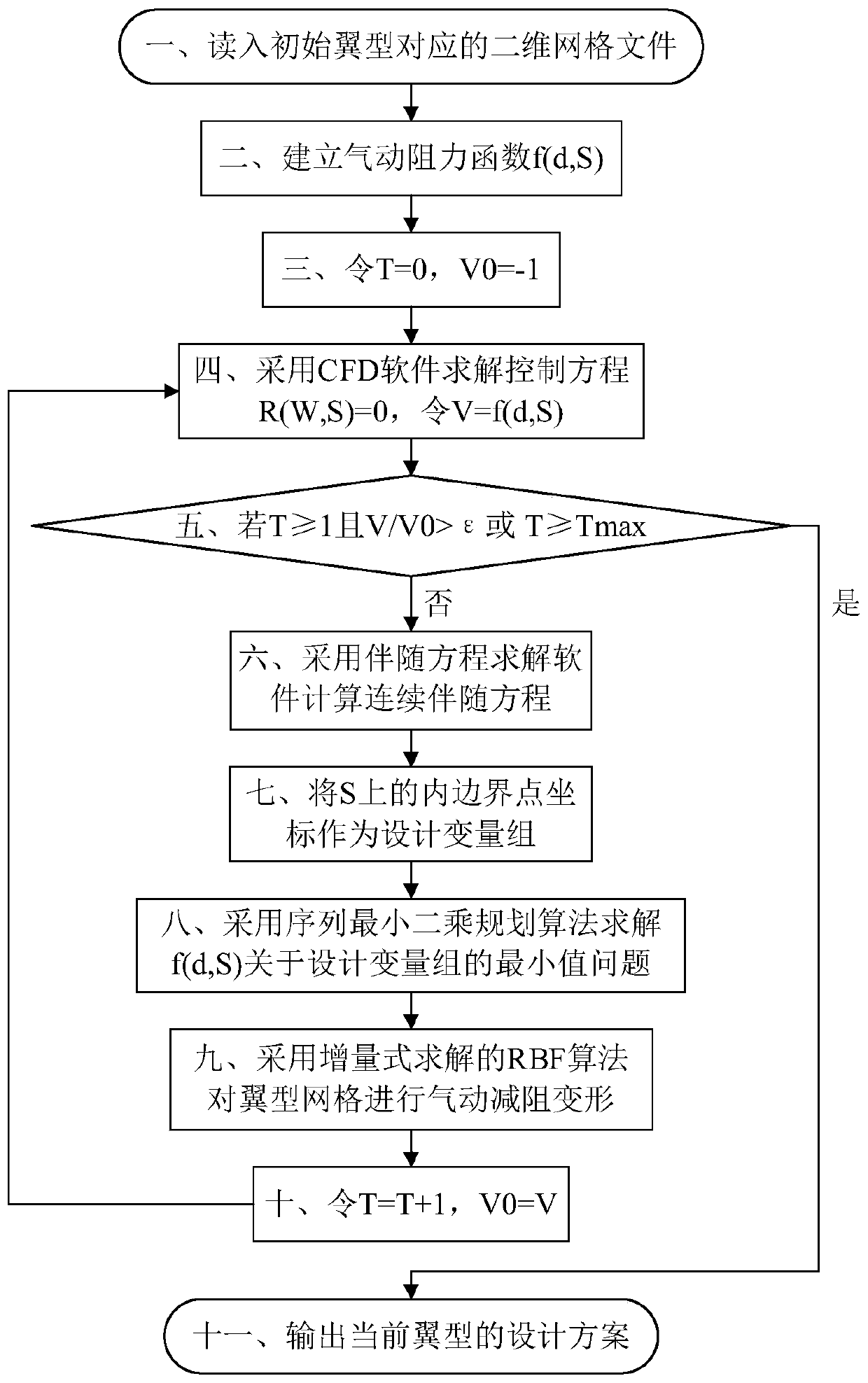
[0073] Such as image 3 As shown, the process flow of the airfoil aerodynamic drag reduction method based on the improved radial basis function deformation algorithm of the present invention includes the following steps:

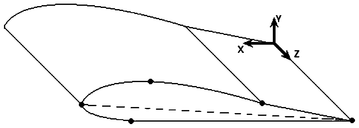
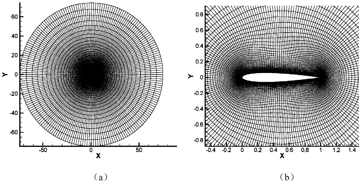
[0074] The first step is to read in the two-dimensional grid file corresponding to the initial airfoil, and the inner boundary of the two-dimensional grid corresponds to the initial airfoil S (that is, the geometric shape of the initial airfoil, such as figure 1 The two-dimensional airfoil surrounded by solid circles), the far-field outer boundary is 20 times the airfoil chord length from the inner boundary (the distance between the front and rear edges of the airfoil, such as figure 1 As shown by the dotted line in ), the two-dimensional mesh of the initial airfoil S is read as figure 2 as shown, figure 2 (a) is a schematic diagram of the overall grid after the two-dimensional grid visualization of the initial airfoil S. The X and Y coordinate axes are ...


PUM


Abstract

The invention discloses an aerofoil aerodynamic drag reduction method based on an improved radial basis function deformation algorithm, and aims to improve the automation degree of aerofoil drag reduction design, further reduce the wind drag coefficient of an aerofoil and improve the drag reduction optimization efficiency. According to the technical scheme, the method comprises the steps of usingall nodes on the geometric boundary of the airfoil profile as the design variables; establishing an airfoil aerodynamic resistance function related to the resistance variable d; solving the minimum value problem of the aerodynamic resistance function f (d, S) about the design variable group by adopting a sequence least square programming algorithm; and obtaining an optimal displacement sequence ofNw inner boundary points on the inner boundary of the grid, and performing aerodynamic drag reduction deformation on the airfoil grid by adopting an incremental solving RBF grid deformation algorithmto obtain an optimal wind drag coefficient or airfoil grid and airfoil geometry of which the airfoil drag reduction reaches the best result within the maximum iteration step number. The method can besuitable for various types of grids, the automation degree of the airfoil profile drag reduction design can be remarkably improved, the drag reduction optimization efficiency is higher, and the result is more accurate.

Description

technical field [0001] The invention belongs to the technical field of aerodynamic drag reduction for aviation vehicles, and in particular relates to an airfoil aerodynamic drag reduction method based on an improved radial basis function (Radial Basis Function, RBF) deformation algorithm. Background technique [0002] In the process of aerodynamic drag reduction design of an aircraft, the wing is the main component that bears lift and drag. The airfoil of the wing section is a very important link in the aerodynamic design. The design of the basic airfoil is related to the pressure of the wing and the fuselage distribution, which has an important influence on the flow pattern of the aircraft. Traditional aircraft and airfoil design methods are mostly based on wind tunnel tests or computational fluid dynamics (Computational Fluid Dynamics, CFD) analysis results, mainly relying on manual trial and error and repeated corrections based on experience. With the development of scie...

Claims


Application Information

Patent Timeline
Patent Type & Authority Applications(China)
IPC IPC(8): G06F17/50G06F17/16
CPCG06F17/16Y02T90/00
Inventor 高翔徐传福熊敏李大力车永刚吴诚堃郭晓威张翔李超蓝龙王思齐王正华
Owner NAT UNIV OF DEFENSE TECH
Why Eureka
Try Eureka