Water vapor capturing device

A capture device and water vapor technology, applied in steam condensation, chemical instruments and methods, separation methods, etc., to achieve the effect of facilitating regeneration operation and ensuring purification efficiency

Pending Publication Date: 2019-12-27
紫石能源有限公司
View PDF0 Cites 1 Cited by
  • Summary
  • Abstract
  • Description
  • Claims
  • Application Information

AI Technical Summary

Problems solved by technology

[0004] The purpose of the present invention is to provide a water vapor capture device that is easy to regenerate to replace the existing molecular sieve purification scheme, thereby solving many disadvantages in the molecular sieve purification process

Method used


Image

  • Water vapor capturing device
  • Water vapor capturing device
  • Water vapor capturing device

Examples


Embodiment Construction

[0043] Embodiments of the present invention are described in detail below, examples of which are shown in the drawings, wherein the same or similar reference numerals designate the same or similar elements or elements having the same or similar functions throughout. The embodiments described below by referring to the figures are exemplary only for explaining the present invention and should not be construed as limiting the present invention.

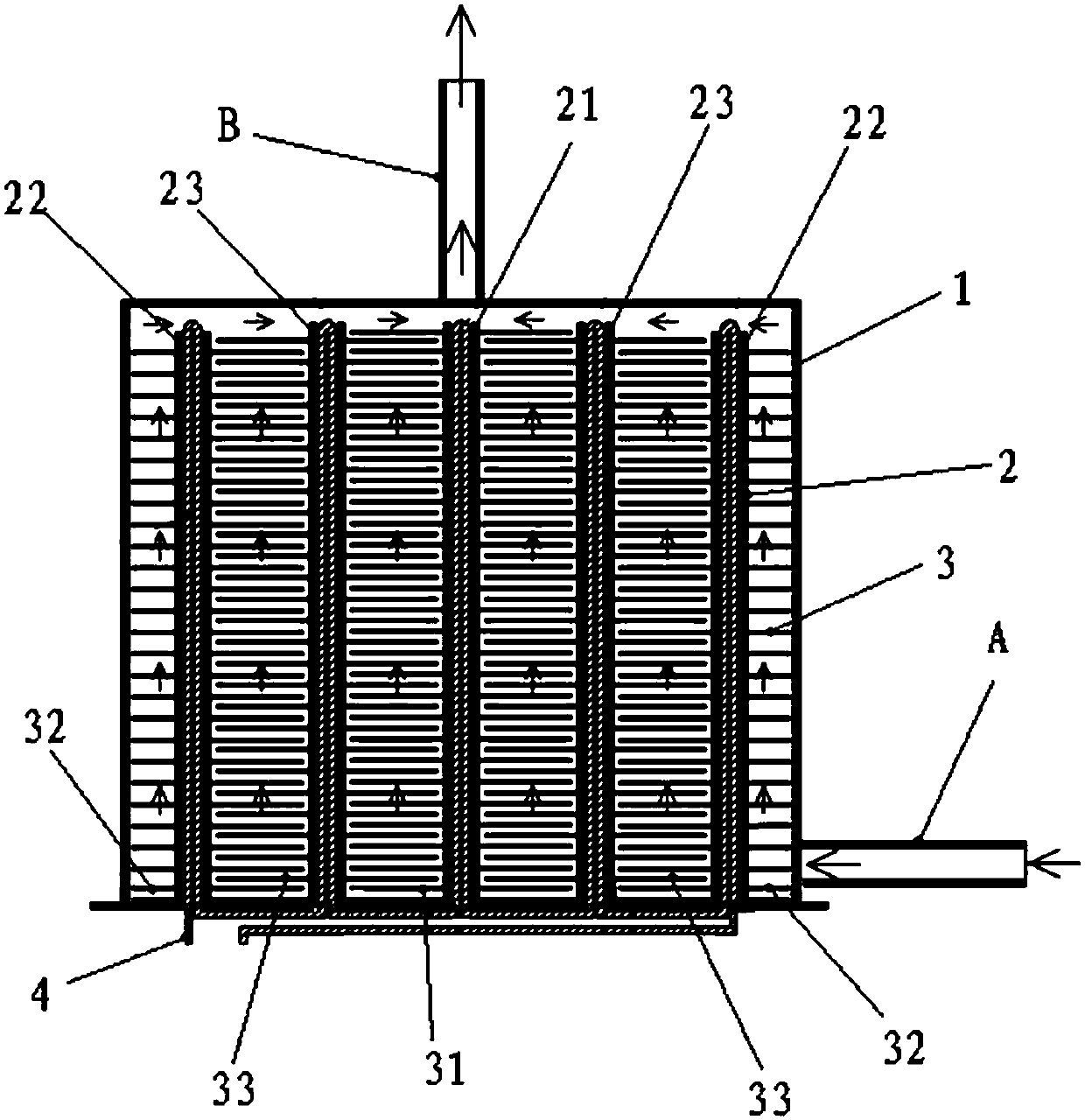
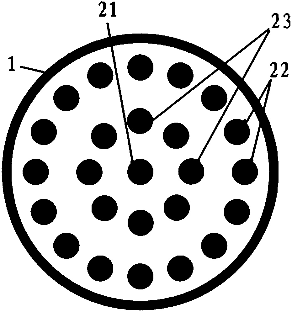
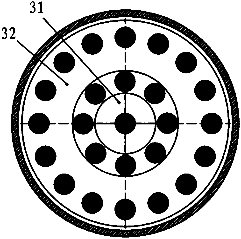
[0044] The present invention provides an embodiment of a water vapor capture device, such as figure 1 As shown, it mainly includes a condensation chamber 1 for capturing water vapor, and a gas inlet A for inputting the gas to be processed is provided on the housing of the condensation chamber 1, for example, the aforementioned electronic gas to be purified and purified can be produced by gas The inlet A flows into the condensation chamber 1; correspondingly, the housing of the condensation chamber 1 is also provided with a gas outlet B f...


PUM


Abstract

The invention discloses a water vapor capturing device, which comprises a condensation cavity used for capturing water vapor. A gas inlet for inputting to-be-treated gas and a gas outlet for outputting treated gas are formed in a shell of the condensation cavity; a column-shaped condensation rod and a plurality of groups of water vapor capture sheets are arranged in the condensation cavity; the water vapor capture sheets are installed on the column-shaped condensation rod and are arranged in a multi-layer staggered mode, wherein gaps are formed between the water vapor capture pieces in each layer. Compared with an existing molecular sieve device, the condensation capture structure provides a larger water vapor contact area, and a large-volume molecular sieve device does not need to be built with a large amount of cost; and moreover, the water vapor is captured by adopting a condensation principle, so that the captured water vapor is converted into solids (such as ice crystals) througha condensation effect, the condensate can be molten only by heating operation in a regeneration process, electronic gas does not need to be consumed, and toxic by-products cannot be introduced or secondarily generated.

Description

technical field [0001] The invention relates to an industrial gas treatment process, in particular to a water vapor capture device. Background technique [0002] Today, with the rapid development of the semiconductor industry, solar energy industry, LED industry, flat panel display industry and optical fiber industry, electronic gases such as arsine are used more and more widely. In the process flow, the purification process of electronic gases is required. It is required to remove impurities quickly and efficiently without introducing new impurities, and to produce less pollutants. The purification equipment is also required to be able to be regenerated online. [0003] At present, molecular sieve devices are generally used to remove water vapor in electronic gases such as arsenic, but the molecular sieve loses its adsorption effect after the micropore inner surface area absorbs water vapor, and the molecular sieve has a limited ability to absorb water vapor per unit volume...

Claims


Application Information

Patent Timeline
Patent Type & Authority Applications(China)
IPC IPC(8): B01D5/00
CPCB01D5/0012
Inventor 赵青松宁红锋
Owner 紫石能源有限公司
Why Eureka
Try Eureka