Tail gas treatment device for waste incineration

A tail gas treatment and waste incineration technology, which is applied in the field of tail gas treatment devices and waste incineration tail gas treatment devices, can solve the problems of reducing the service life of the filter, reducing the effect of waste gas filtration, and increasing the workload of operators, so as to achieve thorough tail gas purification, The effect of improving efficiency

Inactive Publication Date: 2019-12-27
ANHUI SHENGYUN ENVIRONMENT PROTECTION GRP CO LTD
View PDF1 Cites 10 Cited by
  • Summary
  • Abstract
  • Description
  • Claims
  • Application Information

AI Technical Summary

Problems solved by technology

[0005] The purpose of the present invention is to solve the problem that when the tail gas of garbage incineration is processed, a large amount of dust will accumulate on the filter due to long-term use, which will easily reduce the filtering effect of the waste gas, and even cause the equipment to fail to remove dust normally, greatly reducing the efficiency of the filter. The service life will bring economic losses to users; in the process of purifying the exhaust gas of incineration, there are many steps to purify the exhaust gas, which prolongs the time of exhaust gas purification, increases the workload of operators, and also increases the cost of exhaust gas purification ; In addition, in the dust removal and purification stage, it is necessary to manually carry out auxiliary dust removal and tail gas emission detection, which increases the labor force of workers and also affects the health of workers, so a tail gas treatment device for waste incineration is proposed

Method used


Image

  • Tail gas treatment device for waste incineration
  • Tail gas treatment device for waste incineration
  • Tail gas treatment device for waste incineration

Examples


Embodiment Construction

[0025] The technical solutions of the present invention will be clearly and completely described below in conjunction with the embodiments. Apparently, the described embodiments are only some of the embodiments of the present invention, not all of them. Based on the embodiments of the present invention, all other embodiments obtained by persons of ordinary skill in the art without creative efforts fall within the protection scope of the present invention.

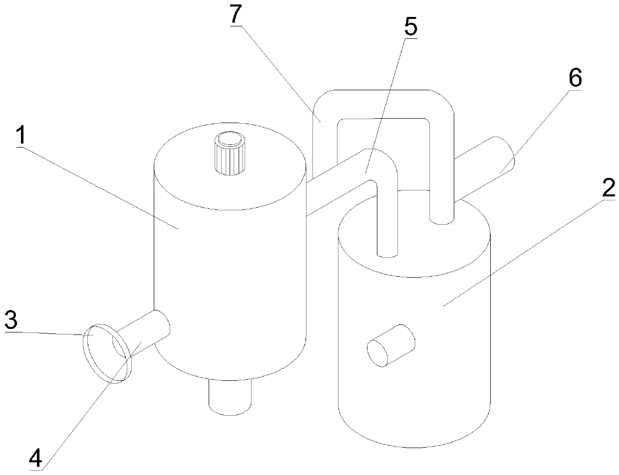
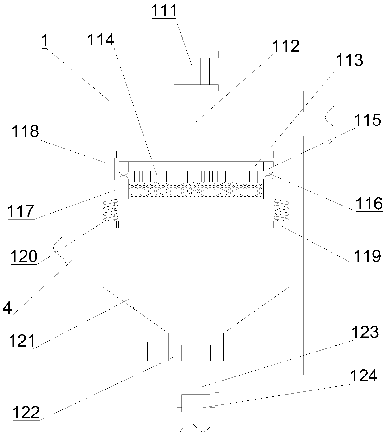
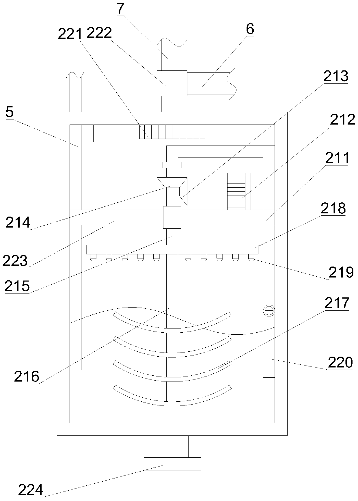
[0026] Such as Figure 1-4As shown, a tail gas treatment device for waste incineration includes a dust removal tank 1 and a purification tank 2, the bottom of the side wall of the dust removal tank 1 communicates with the intake pipe 4, and the feed end of the intake pipe 4 is connected with the intake cover 3, The discharge end of the top of the other side wall of the dust removal tank 1 is connected to the feed end of the communication pipe 5, the discharge end of the communication pipe 5 extends to the bottom of the puri...


PUM


Abstract

The invention discloses a tail gas treatment device for waste incineration. The device comprises a dust removal tank and a purification tank, wherein the gas outlet end of the top of the purificationtank communicates with an exhaust pipe and a circulating pipe through a three-way electromagnetic valve, while the other end of the circulating pipe is connected with a communicating pipe; a discharging pipe is arranged at the discharging end of the bottom of the purification tank, and a tail gas dust removal mechanism and a tail gas purification mechanism are arranged in the dust removal tank andthe purification tank respectively; the output end of the first motor is connected with the first rotating shaft; the bottom end of the first rotating shaft extends into the dust removal tank and isrotationally connected with the dust removal tank; the bottom end of the first rotating shaft is connected with the middle of a transverse plate, brush hairs are arranged on the bottom face of the transverse plate, connecting blocks are arranged on the two sides of the transverse plate respectively, first magnets are arranged on the bottom faces of the connecting blocks, the inner wall of the dustremoval tank is connected with a filtering piece through a limiting assembly, and a weight sensor is arranged at the bottom of the dust collection cover. The device has the advantages that dust removal and ash removal are facilitated, the tail gas purification efficiency is high, automatic operation is improved, and labor output is reduced.

Description

technical field [0001] The invention belongs to the technical field of waste incineration, and relates to a tail gas treatment device, in particular to a tail gas treatment device for waste incineration. Background technique [0002] Waste incineration is the process of reducing the volume of waste through oxidation at high temperature through appropriate thermal decomposition, combustion, melting and other reactions, and turning it into residue or molten solid matter. [0003] The comparative document CN201822168443.8 discloses a garbage incineration equipment, which relates to the field of garbage treatment, and solves the problem that the spray gun of the existing garbage incineration equipment is likely to affect the leachate atomization effect when the pressure is unstable and the return of the leachate will affect the gas consumption of other users. The key points of the technical solution include the incinerator, the static frame, the collection box arranged under the...

Claims


Application Information

Patent Timeline
Patent Type & Authority Applications(China)
IPC IPC(8): B01D46/00B01D46/10B01D53/78
CPCB01D46/10B01D53/78B01D46/681
Inventor 季科潘岚松
Owner ANHUI SHENGYUN ENVIRONMENT PROTECTION GRP CO LTD
Why Eureka
Try Eureka