Eureka AIR delivers breakthrough ideas for toughest innovation challenges, trusted by R&D personnel around the world.

Aluminum cylinder head guide pipe reaming process device

A process device and cylinder head technology, applied in reaming devices, reaming devices, manufacturing tools, etc., can solve problems such as unstable processing, hidden safety hazards, and affecting the accuracy of reaming processing, so as to improve accuracy and stability, The effect of eliminating potential safety hazards

Inactive Publication Date: 2019-12-27
ANHUI HIGH TECH POWER TECH
View PDF5 Cites 0 Cited by
  • Summary
  • Abstract
  • Description
  • Claims
  • Application Information

AI Technical Summary

Problems solved by technology

[0003] In the traditional fine reaming process, the cylinder head is placed on a drilling machine, the reamer handle is clamped by the drill chuck, and the left hand supports the cylinder head and the right hand feeds. There are many defects in this processing process: (1) The positioning surface of the cylinder head The lower end is just a flat plate, which has a large degree of freedom when placed, and is in a state of under-positioning. When the cylinder head is reamed, it is equivalent to no positioning, which makes the process very unstable and affects the machining accuracy of the reaming hole; (2) When reaming, the reamer is clamped When entering, the worker must hold his palm to align with the conduit hole. The disadvantage of this processing method is the unstable positioning and clamping state, which makes the processing process have relatively large safety hazards; (3) This kind of relying on the operator to control the processing The way of precision leads to low processing efficiency of the cylinder head, which affects the delivery time of users; (4) processing depends on the operation level of workers, making the product quality unstable, and the cylindricity of the hole system cannot be guaranteed

Method used


Image

  • Aluminum cylinder head guide pipe reaming process device
  • Aluminum cylinder head guide pipe reaming process device
  • Aluminum cylinder head guide pipe reaming process device

Examples


Embodiment Construction

[0022] The content of the present invention will be described below in conjunction with specific embodiments.

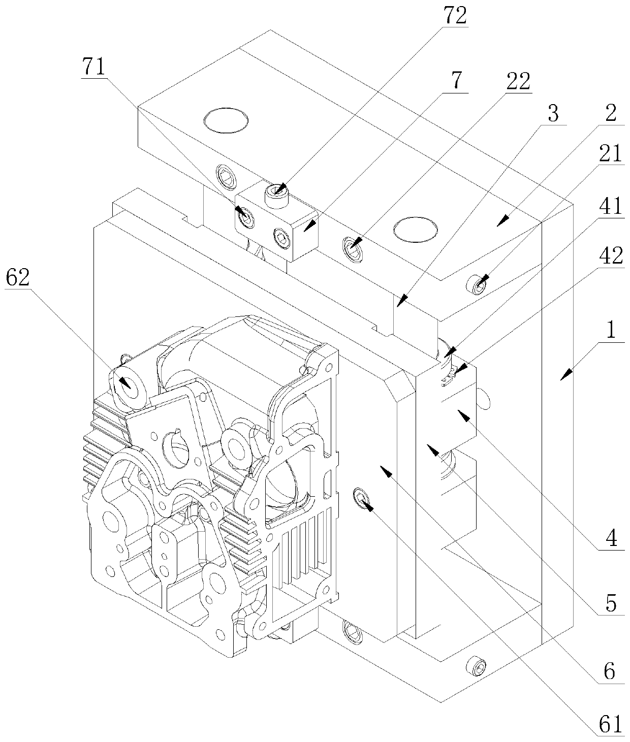
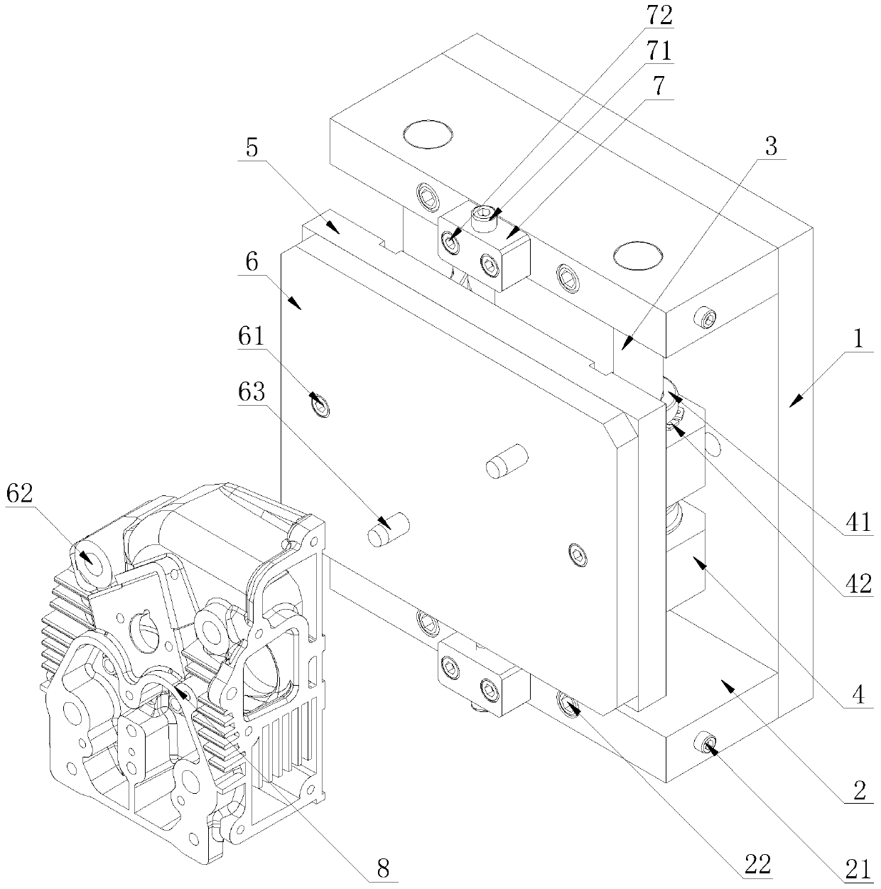
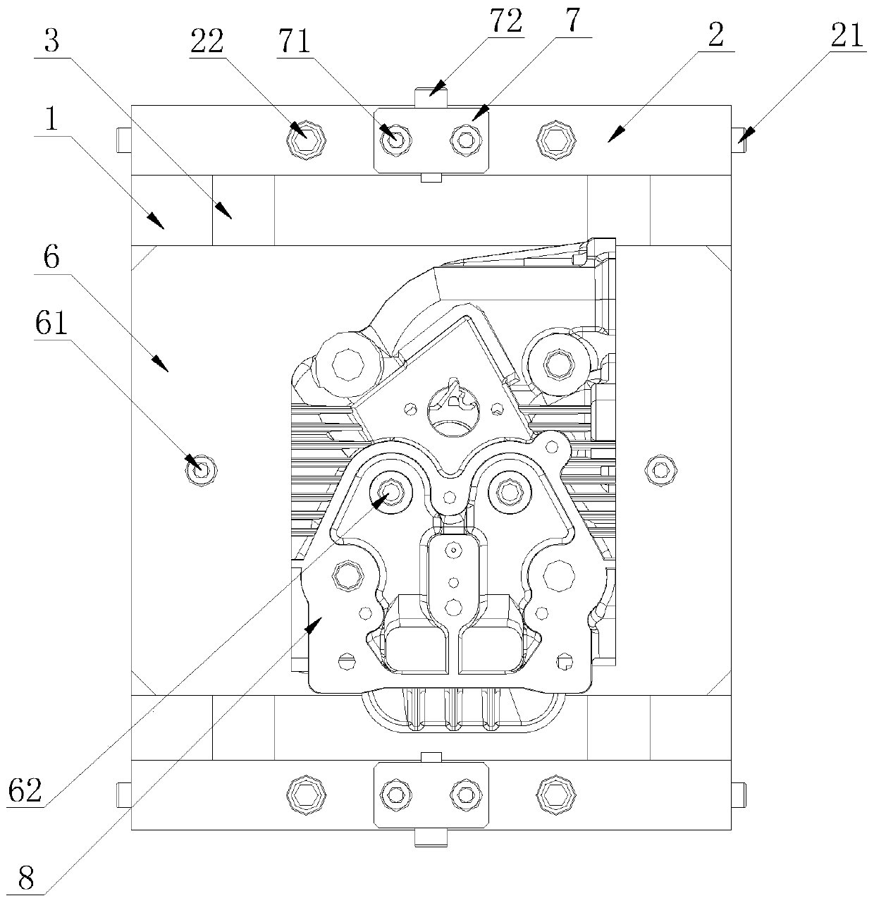
[0023] figure 1 It is a schematic diagram of the clamping structure of the process device of the present invention, figure 2 It is a schematic structural view of the process device of the present invention, such as figure 1 and figure 2 As shown, the process device of the present invention is installed on the machine tool for positioning and clamping the cylinder head 8, including: a tooling base plate 1 fixed on the machine tool, a pair of support plates symmetrically fixed on the top and bottom of the tooling base plate 1 2. The vertical shaft 3 installed between the support plates 2, the bearing seat 4 slidingly connected with the vertical shaft 3, the sliding table bottom plate 5 fixed on the outer wall of the bearing seat 4, and the sliding table bottom plate fixed on the bottom sliding table 5 on the positioning plate 6. There are many vertical shafts 3, ...


PUM


Abstract

The invention relates to an aluminum cylinder head guide pipe reaming process device. The device is mounted on a machine tool and used for positioning a clamping cylinder cover, and comprises a tool bottom plate fixed on the machine tool, a pair of supporting plates symmetrically fixed at the top and the bottom of the tool bottom plate, vertical shafts arranged between the supporting plates, a bearing seat slidably connected with the vertical shafts, a sliding table bottom plate fixed on the outer wall of the bearing seat, and a positioning plate fixed on the sliding table bottom plate; a plurality of vertical shafts are symmetrically arranged; and the top of the positioning plate is provided with two positioning pins, and the length of the positioning pins are greater than one-half of themaximum cross-sectional width of the cylinder cover. According to the device, the positioning plate and the positioning pins are arranged to realize complete positioning of the two pins on one surface, flexible scheduling of the position of the positioning plate is achieved through the arrangement of the vertical shafts and bearings, the bearing seat is arranged to contain the bearings and support the sliding table bottom plate, and the positioning accuracy and stability are improved by arranging stroke stop blocks and limiting the parts of the parts.

Description

technical field [0001] The invention relates to the technical field of fixtures, in particular to an aluminum cylinder head conduit reaming process device. Background technique [0002] The cylinder head of a diesel engine is one of the key components of the four-stroke internal combustion engine. The aluminum cylinder head is a working part installed on the cylinder. It participates in the sealing of the cylinder space and the composition of the combustion chamber. It is used to install the intake and exhaust valves and the installation of the intake and exhaust pipes. It can withstand the combustion pressure and conduct the room temperature in the cylinder. A cylinder block component that realizes heat storage and heat dissipation functions. The aluminum cylinder head is also the leading accessory of our company's internal combustion engine from casting to metal processing finished product input to output. Among them, the two valve guide holes of the aluminum cylinder hea...

Claims


Application Information

Patent Timeline
Patent Type & Authority Applications(China)
IPC IPC(8): B23D75/00
CPCB23D75/00
Inventor 占长安唐俊林兰天余明
Owner ANHUI HIGH TECH POWER TECH
Why Eureka
Eureka Blog
Learn More