Swimming channel for allowing migration fishes to pass

A technique of migration and passage, applied in the field of travel, to achieve the effect of promoting harmonious development, easy to manufacture, and simple in structure

Pending Publication Date: 2019-12-27
ZHEJIANG UNIV OF TECH
View PDF0 Cites 3 Cited by
  • Summary
  • Abstract
  • Description
  • Claims
  • Application Information

AI Technical Summary

Problems solved by technology

At present, fishways pass through fishholes in the shape of rectangles and vertical seams. However, existing stat...

Method used


Image

  • Swimming channel for allowing migration fishes to pass
  • Swimming channel for allowing migration fishes to pass
  • Swimming channel for allowing migration fishes to pass

Examples


Embodiment 1

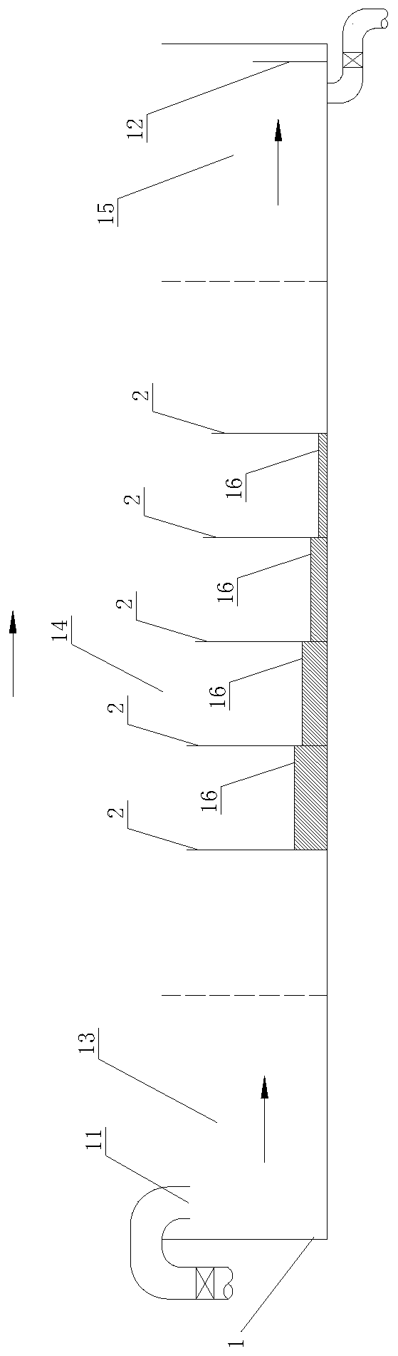
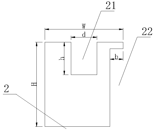
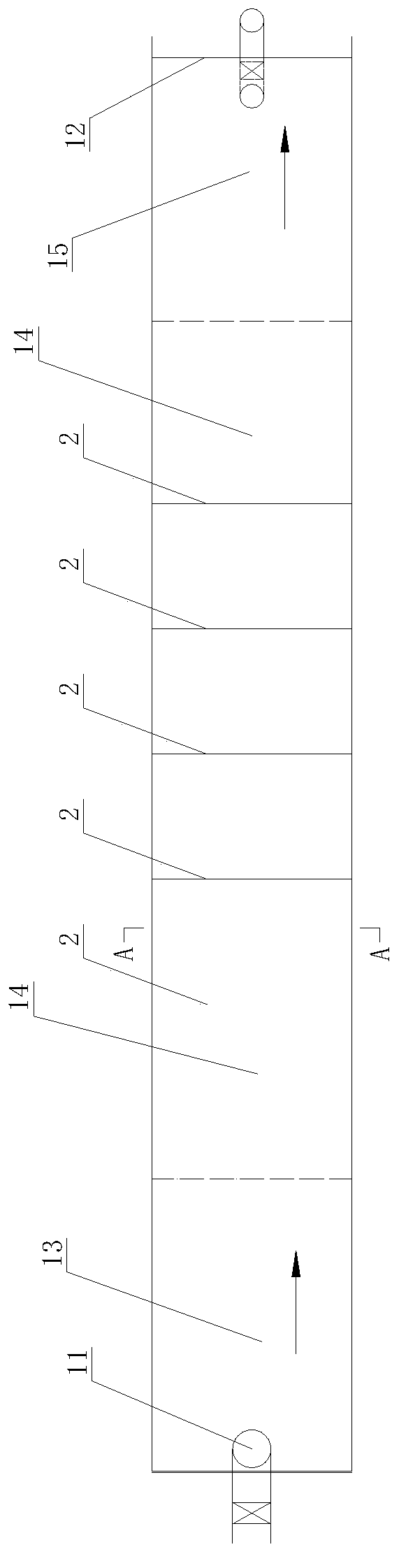
[0016] Embodiment 1 A swimming channel suitable for migratory fish according to the present invention includes a migratory channel 1 and water inlet pipes 11 and outflow dams 12 respectively arranged at both ends of the migratory channel, wherein the water inlet pipe 11 is arranged in the migratory channel 1 upstream, the outflow dam 12 is arranged at the downstream end 1 of the migratory passage 1; the migratory passage 1 is divided into test areas arranged sequentially along the water flow direction by a plurality of water retaining plates 2 lower than the upper edge of the waterway, and The top on the water-retaining board 2 is provided with a sunken rectangular groove 21, so that the top edge of the water-retaining board 2 forms a notch weir; gap, so that there is a vertical seam 22 for fish to pass between the inset side of the water retaining plate and the channel wall, wherein the bottom end of the vertical seam 22 extends to the bottom plate of the water channel, and th...

Embodiment 2

[0020] Embodiment 2 In the three-dimensional weir flow and two-dimensional wall jet combined fishway described in the present invention, the device body is a large-scale glass fishway water tank. The width ratio e=b / W=0.167, the notch weir height h is 250mm, the width d is 200mm, and the weir width ratio k=d / W=0.33. Migratory channel 1 is divided into upstream section 13, midstream section 14, and downstream section 15. The notch forming the notch weir is located on the top of the water retaining plate. Part of the flow in the pool, the energy of the discharged water mainly depends on the downstream water cushion to dissipate the energy, which is suitable for fish that like to jump; The water pool diffuses and dissipates energy in the form of wall jets, and is not affected by water level fluctuations. It is used to pass large and medium-sized fish that can adapt to more complex flow regimes. According to the gap width ratio e (e=b / W), the weir width ratio k (k=d / W) and the po...


PUM


Abstract

The invention discloses a swimming channel for allowing migration fishes to pass. The swimming channel for allowing the migration fishes to pass comprises a migration channel and a water inlet pipe and a flow outlet dam which are arranged at the two ends of the migration channel respectively, the water inlet pipe is arranged on the upstream side of the migration channel, and the flow outlet dam isarranged at the downstream end of the migration channel; the interior of the migration channel is partitioned into testing areas which are sequentially arranged in the water flow direction through multiple water retaining insertion plates lower than the upper edge of a water channel, the tops of the water retaining insertion plates are provided with submerged rectangular grooves, and then notch weirs are formed on the top edges of the water retaining insertion plates; and one side edge of each water retaining insertion plate is concaved inwards to form a gap, a vertical seam is reserved between the inward concave side edge of each water retaining insertion plate and the water channel groove wall, the bottom end of each vertical seam extends to a water channel bottom plate, the upper end of each vertical seam extends to the upper edge of the corresponding water retaining insertion plate, and each vertical seam has two arrangement modes including the same side or the different side. Theswimming channel for allowing the migration fishes to pass has the beneficial effects of being simple in structure, easy to manufacture, economical, practical, excellent in hydraulic characteristic and capable of generating a turbulence zone and a vortex zone which are needed by fish migration.

Description

technical field [0001] The invention relates to a swimming channel suitable for migratory fish to pass through. Background technique [0002] my country's coasts and rivers are rich in fish resources, and there are many migratory fishes. One type is the fish that usually live in the ocean. When they reach sexual maturity, they trace back to inland rivers or their affiliated lakes in groups during the annual breeding season. The other type is fish that usually live in fresh water, and when they are sexually mature, they descend into the river to spawn in the sea (mainly eel) ). The former are called anadromous fishes, and the latter are called downriver migratory fishes. In addition, there are semi-migratory fishes (herring, grass carp, silver carp, bighead carp, etc.) that migrate between rivers and lakes or between main streams and tributaries for spawning, feeding, overwintering and other purposes. In order to communicate the migration channels of fish and maintain biolog...

Claims


Application Information

Patent Timeline
IPC IPC(8): E02B8/08
CPCE02B8/08E02B8/085Y02A40/60
Inventor 董志勇余俊鹏
Owner ZHEJIANG UNIV OF TECH
Why Eureka
Try Eureka