

Particle reconstruction method and device in three-dimensional flow field, electronic device and storage medium
A three-dimensional flow field and particle technology, applied in the field of flow field, can solve the problem of insufficient accuracy of the three-dimensional particle field, and achieve the effect of high reconstruction accuracy, high accuracy and small amount of calculation.
- Summary
- Abstract
- Description
- Claims
- Application Information
AI Technical Summary
Problems solved by technology
Method used
Image

Examples
example 1
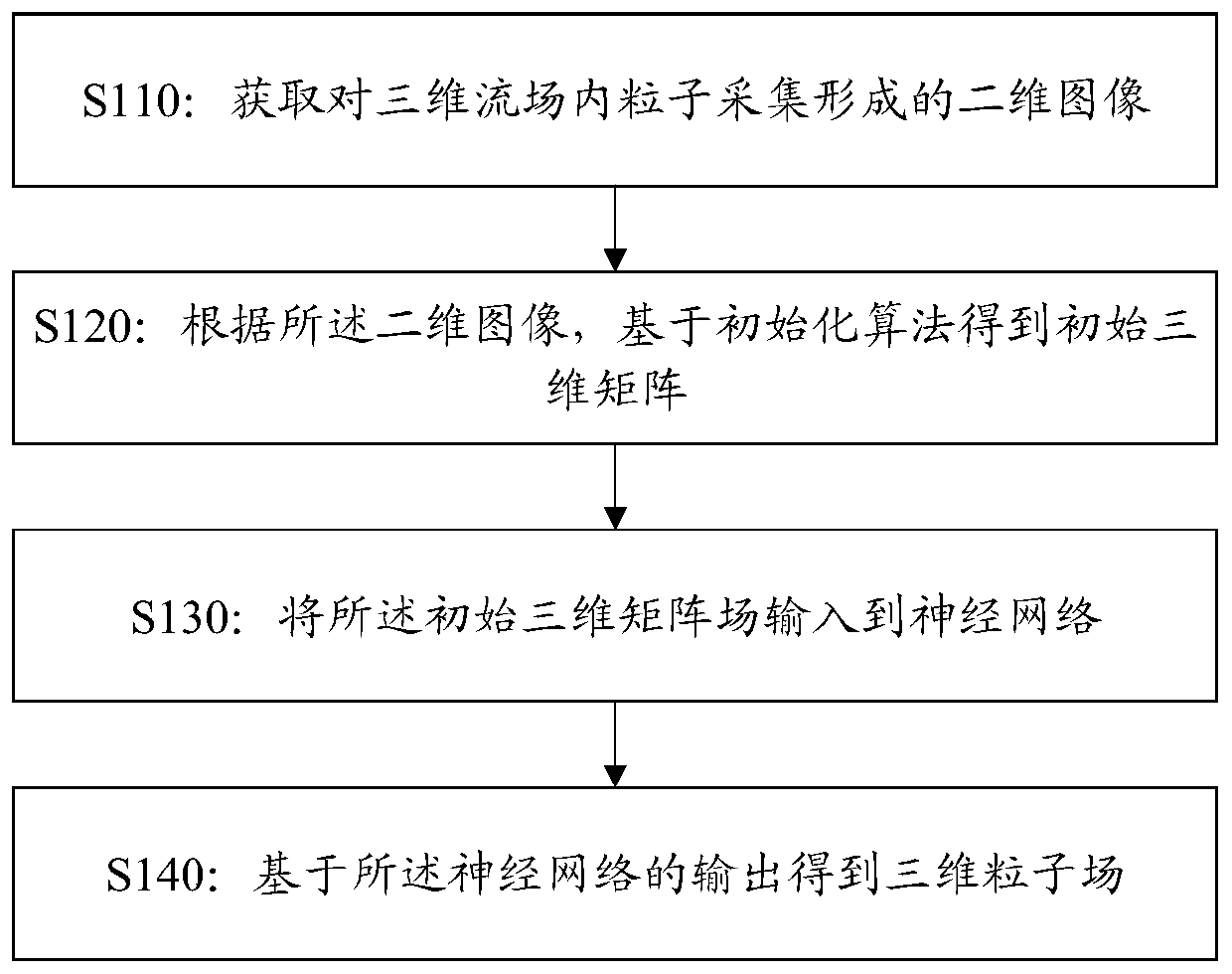
[0121] Such as Figure 8 As shown, this example provides a particle reconstruction method in a three-dimensional flow field, including:
[0122] The first step is the initialization of the three-dimensional particle field. After reading in the image captured by the camera, use an initialization algorithm to obtain the initial three-dimensional matrix. There are many initialization algorithms, including but not limited to: MLOS algorithm, MFG algorithm or constant initialization algorithm. The obtained initial three-dimensional matrix can be expressed as a three-dimensional matrix. The initial three-dimensional matrix does not provide accurate information on the position and shape of the particles, but only projects the particles captured on the two-dimensional image in the direction of the line of sight to obtain a three-dimensional matrix. The initial three-dimensional matrix is used as the input of the three-dimensional reconstruction algorithm to carry out the three-dim...
example 2
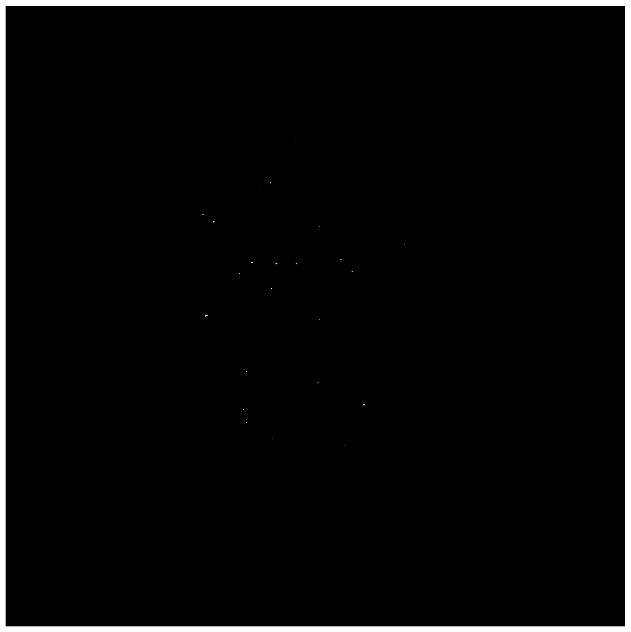
[0131] The image captured by the camera is read in, and the initialization method is used to obtain the initial three-dimensional matrix. The method used in this embodiment is the MLOS algorithm. The size of the initial three-dimensional matrix of particles after initialization is 256×256×128, see the cross-section image 3 . As shown in the figure, there is no obvious particle shape and position information in the initial three-dimensional matrix
[0132] The matrix block (i.e. block processing) of the initial three-dimensional matrix can be as follows:
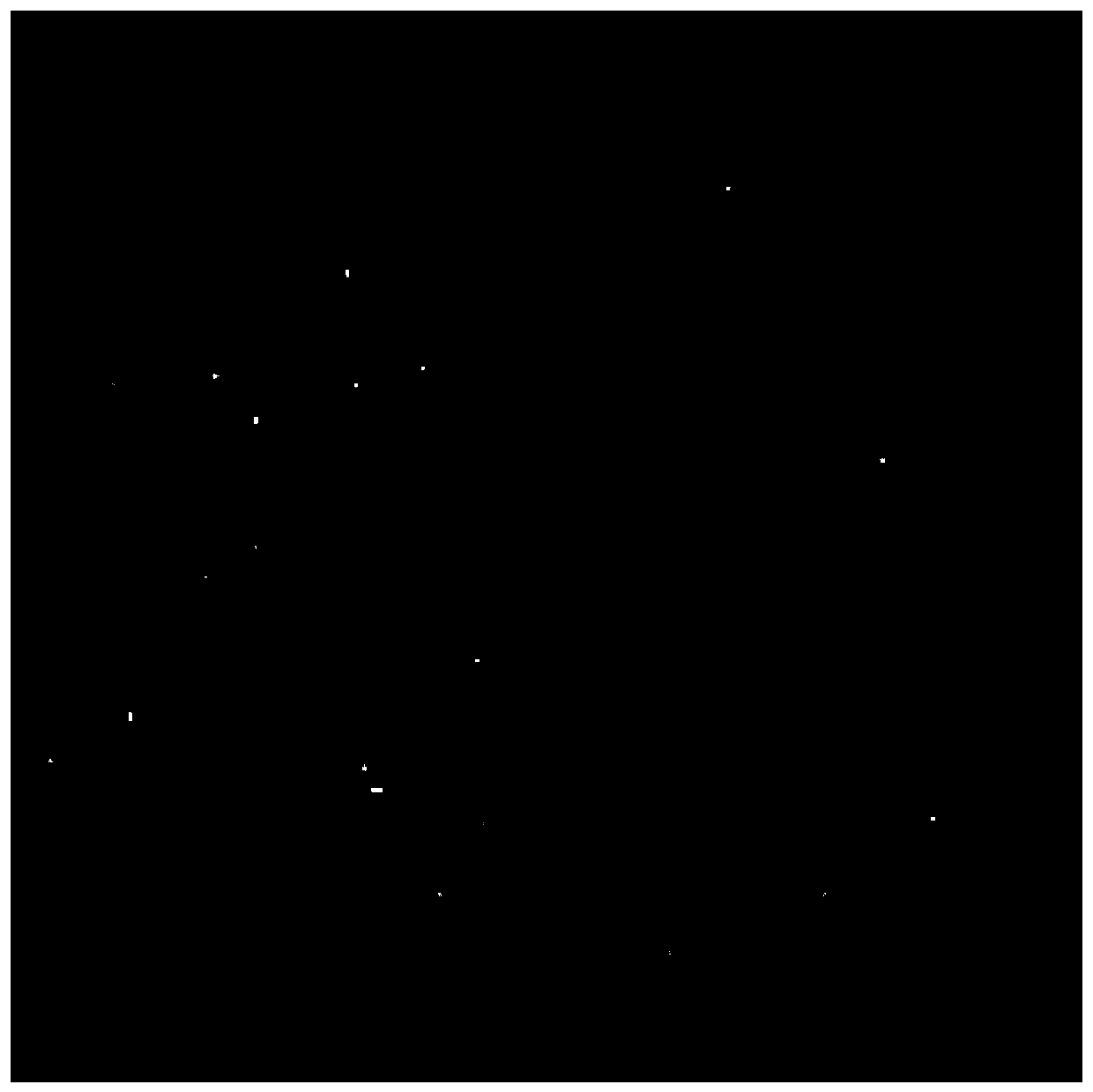
[0133] The block processing of the initial three-dimensional matrix may include: dividing the initial three-dimensional matrix into small blocks of 64×64×32. In this embodiment, the field after the initialization of the MLOS algorithm is divided into 64 blocks (4×4×4) according to the method of adjacent block division (ie, block by block). For the section image after block, see Figure 4 .
[0134] Applying the convolut...
example 3
[0139] This example also provides a neural network that can be used for 3D reconstruction of particles based on the initial 3D matrix. The structure of the neural network can be as follows Figure 9 As shown, including: input layer; middle layer; output layer.
[0140] The neural network may include predetermined network layers, for example, 12 network layers, the first network layer is an input layer, the last network layer is an output layer, and the remaining 10 network layers are intermediate layers.
[0141] The network layers are connected layer by layer to form the network architecture.
[0142] Figure 9 Shown is a 3D convolutional neural network with 12 network layers. The size of the input layer and the output layer can be both 64×64×32×1, the size of the convolution kernel can be 3×3×3, the activation function of the last layer is the Sigmoid function, and the activation function of the other network layers can be used Linear Correction Unit (Relu) function. The...
PUM
 Abstract
Description
Claims
Application Information