3D printing method and 3D printing equipment

A 3D printing and equipment technology, which is applied in the field of 3D printing, can solve the problems of poor mechanical properties at seams, and achieve the effects of fast forming speed, avoiding stress concentration, and reducing the number of irradiations

Pending Publication Date: 2019-12-31
李佳
View PDF4 Cites 1 Cited by
  • Summary
  • Abstract
  • Description
  • Claims
  • Application Information

AI Technical Summary

Problems solved by technology

[0005] In order to overcome the technical problem of poor mechanical properties of current 3D printing products at the joints corresponding to digital micromirror components, the present invention provides a new 3D printing method and system, and 3D printing equipment

Method used


Image

  • 3D printing method and 3D printing equipment
  • 3D printing method and 3D printing equipment
  • 3D printing method and 3D printing equipment

Examples


Embodiment Construction

[0062] In order to make the object, technical solution and advantages of the present invention more clear, the present invention will be further described in detail below in conjunction with the accompanying drawings and embodiments. It should be understood that the specific embodiments described here are only used to explain the present invention, not to limit the present invention.

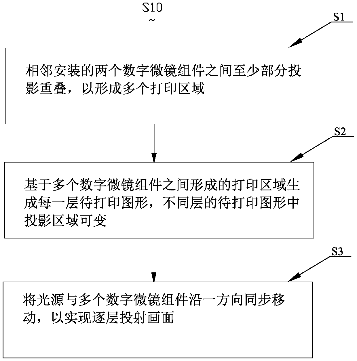
[0063] see figure 1 , the first embodiment of the present invention provides a 3D printing method S10, the 3D printing method S10 is carried out based on a 3D printing device, and the 3D printing method is projected in the form of a surface light source through a digital micromirror assembly, Described 3D printing method comprises the steps:

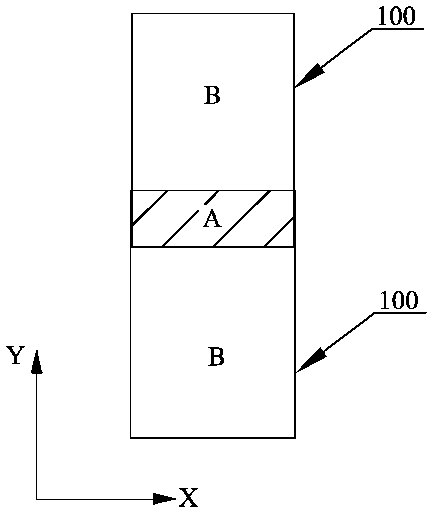
[0064] Step S1, the light emitted from the light source passes through at least two digital micromirror devices (DMDs) installed adjacently to form multiple printing areas, wherein the multiple printing areas overlap at least partially to form multiple ov...


PUM


Abstract

The invention relates to the technical field of 3D printing, in particular to a 3D printing method and 3D printing equipment. The 3D printing method comprises the steps that (1) at least partial projections overlap between two digital micromirror assemblies arranged adjacently to form a plurality of printing areas; (2) each layer of graph to be printed is generated on the basis of the printing areas formed among the plurality of digital micromirror assemblies, wherein projection areas in the graphs to be printed of different layers are variable; and (3) a light source and the plurality of digital micromirror assemblies are synchronously moved along one direction so as to realize layer-by-layer picture projection. By using the 3D printing method, the projection overlapping areas among the plurality of digital micromirror assemblies can be dispersed, so that stress concentration is avoided, and the mechanical property of a final product is improved.

Description

【Technical field】 [0001] The invention relates to the technical field of 3D printing, in particular to a 3D printing method and 3D printing equipment. 【Background technique】 [0002] The biggest disadvantage of 3D printing at present is that the production speed is slow, which makes expensive 3D printing equipment bought back. Because of the low output, the cost cannot be diluted, resulting in expensive 3D printing products. The present invention attempts to solve this problem. The current more popular 3D printing methods are as follows: FDM (Fused Deposition Modeling, melt extrusion molding), SLA (Stereo Lithography Apparatus, stereolithography), SLS (PrintingSelective LaserSintering, selective laser sintering), SLM (Selective Laser Melting, selective laser melting), liquid crystal projection, DLP (Digital Light Processing, digital light processing), each of which has great limitations. [0003] Taking SLS as an example, the laser point light source irradiates plastic pow...

Claims


Application Information

Patent Timeline
Patent Type & Authority Applications(China)
IPC IPC(8): B29C64/153B29C64/264B29C64/393B33Y10/00B33Y30/00B33Y50/02
CPCB29C64/153B29C64/264B29C64/393B33Y10/00B33Y30/00B33Y50/02
Inventor 李佳
Owner 李佳
Why Eureka
Try Eureka