Multifunctional ultra-large-stroke yarn storage and unwinding device

A yarn storage device and multi-functional technology, which is applied to the yarn storage device of three-dimensional braiding machine and two-dimensional field, can solve the problems of large gap, large friction force and high noise in the pay-off brake, so as to achieve no gap in the disconnection brake, The effect of adjustable friction tension

Pending Publication Date: 2019-12-31
XUZHOU HENGHUI BRAIDING MACHINE
View PDF1 Cites 0 Cited by
  • Summary
  • Abstract
  • Description
  • Claims
  • Application Information

AI Technical Summary

Problems solved by technology

[0006] The purpose of the present invention is to provide a multi-functional super-long-stroke yarn storage and release device, which solves the problems of small stroke, large friction force, large clearance of wire-releasing brakes, large noise, short service life and ineffective parking when the thread is broken in the existing knitting machine spindle. The problem

Method used


Image

  • Multifunctional ultra-large-stroke yarn storage and unwinding device
  • Multifunctional ultra-large-stroke yarn storage and unwinding device
  • Multifunctional ultra-large-stroke yarn storage and unwinding device

Examples


Embodiment 1

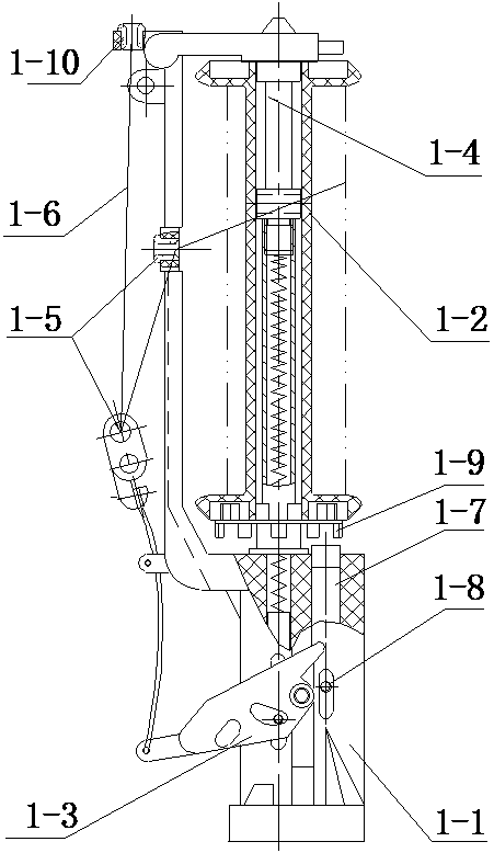
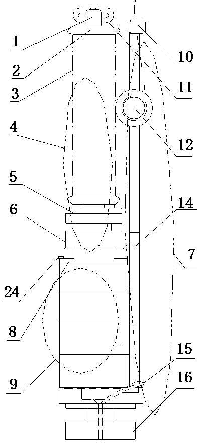
[0044] Embodiment 1: The yarn unwinding device of the present invention includes: a photosensitive communication signal acquisition device 7, a retractable yarn storage drive device assembly 9 and a constant tension wire release device 4; the retractable yarn storage drive device assembly 9 is installed on the optical communication signal On the spindle seat 16 of the collection device 7, the constant tension pay-off device 4 is located at the upper end of the retractable and storage yarn drive device assembly 9; the bolt 24 passes through the yarn storage shaft seat 8 of the constant tension release device 4 and the yarn storage drive The device 9 is connected to the spindle 16 of the optical communication signal acquisition device 7 .

[0045] The photosensitive communication signal acquisition device 7 includes: a spindle base 16, a light conductor 15, a spindle bar 14, a lower thread passer 12 and an upper thread passer 10; a spindle bar 14 is connected to one side of the u...

Embodiment 2

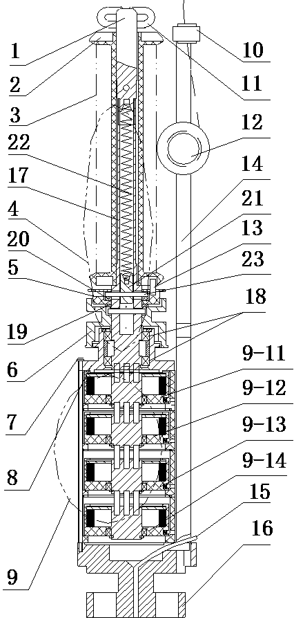
[0065] Embodiment 2: There are four retractable and storage yarn drive devices 9; the four retractable and storage yarn drive devices 9 are fixed in series by bolts; the first drive device 11, the second drive device 12, and the third drive device 13 and the fourth driving device 14 are sequentially connected in series by bolts from top to bottom.

[0066] The dial shaft 9-2 protruding from the top of the retractable yarn storage drive device 9 below is inserted into the dial shaft hole 9-6 at the bottom of the retractable yarn storage drive device 9 above.

[0067] The dial shaft 9-2 of the uppermost yarn storage driving device 9 is inserted into the positioning hole on the lower end surface of the yarn storage device shaft 17 of the constant tension pay-off device 4 .

[0068] The rotor shaft 9-5 of the retractable and storage yarn driving device 9 rotates and drives the yarn storage device shaft 17 to rotate simultaneously through the dial shaft 9-2; tension stroke.

[00...


PUM


Abstract

The invention discloses a multifunctional ultra-large-stroke yarn storage and unwinding device, and belongs to a yarn storage and unwinding device of a two-dimensional and three-dimensional knitting machine. The yarn unwinding device comprises a light sensing communication signal acquisition device, a winding and unwinding yarn storage driving device assembly and a constant tension unwinding device; the winding and unwinding yarn storage driving device assembly is installed on a spindle seat of the light sensing communication signal acquisition device, and the constant tension unwinding deviceis located at the upper end of the winding and unwinding yarn storage driving device assembly; and a bolt penetrates through the yarn storage device shaft seat of the constant-tension unwinding device and the winding yarn storage driving device to be connected to the spindle seat of the light sensing communication signal acquisition device. The multiple groups of driving devices are connected inseries to increase the winding and unwinding stroke of the yarn storage device by four times, when the torsion of the multiple groups of driving devices reaches the limit, the yarn storage device overcomes the rated expansion force and friction and can keep unwinding of yarns, and a purpose of winding and unwinding the yarns continuously with over-large stroke and constant tension, noises do not exist, and the service life is long. The multifunctional ultra-large-stroke yarn storage and unwinding device has the advantages that an optical fiber acquisition signal controls the device to stop sensitively when yarns are broken, faults are positioned accurately, the energy is saved, consumption is reduced, and the device has lots of functions; and two-dimensional and three-dimensional weaving quality is improved, and a weaving range is expanded.

Description

technical field [0001] The invention relates to a yarn storage and release device for a two-dimensional and three-dimensional knitting machine, in particular to a multifunctional and super-large-stroke yarn storage and release device. Background technique [0002] At present, the high-speed machine spindles generally used in braiding machines are usually as figure 1 As shown, it is provided with a spindle bar (1-1), a bobbin (1-2), a thread pendant (1-3), a bobbin shaft (1-4), a porcelain eye (1-5), and a spindle bar ( 1-1) is provided with a bobbin shaft (1-4), the bobbin (1-2) is set on the bobbin shaft (1-4), and the thread pendant (1-2) is set on the spindle bar (1-1 ), one end of the thread pendant (1-3) is provided with a porcelain eye (1-5), and the spindle bar (1-1) is provided with a porcelain eye (1-5), and the yarn (1-6) passes through the spindle during work. Rod porcelain eyes (1-5), then bend through the thread drop porcelain eyes (1-5), and release the wire ...

Claims


Application Information

Patent Timeline
Patent Type & Authority Applications(China)
IPC IPC(8): D04C3/02D04C3/14
CPCD04C3/02D04C3/14
Inventor 韩百峰陈兵刘建峰韩长江
Owner XUZHOU HENGHUI BRAIDING MACHINE
Why Eureka
Try Eureka