Suspension embroidery frame device of computerized embroidery machine

An embroidery machine and embroidery frame technology, applied in the field of a computerized embroidery machine suspended embroidery frame device, can solve the problems of easy wear, reduced life of the embroidery frame, wear of the embroidery frame components, etc. The effect of running precision

Pending Publication Date: 2019-12-31
ZHEJIANG YUELONG SEWING EQUIP
View PDF2 Cites 0 Cited by
  • Summary
  • Abstract
  • Description
  • Claims
  • Application Information

AI Technical Summary

Problems solved by technology

At present, the existing embroidery machine frame has many forms: one is the traditional embroidery frame, which is pasted on the platen plane by felt. This method has the following defects: 1. Due to the friction between the embroidery frame and the platen plane If the embroidery frame exists, it will cause unstable operation of the embroidery frame on the plane. In the case of high embroidery quality, this method will not be fully realized; 2. Due to the long-term friction movement of the embroidery frame on the plane, the embroidery frame components will be worn out, and the noise will be The gradual increase will lead to a decrease in the life of the embroidery frame, and ultimately it will not be possible to achieve high-quality, high-density and efficient embroidery movement; 3. The motor load is large
This scheme uses the bearing of the car body to lift the frame to realize the floating movement of the frame, which has the advantage of small frictional resistance between the guide rail and the frame plate during the movement of the embroidery frame. The disadvantages are: 1. The bearing and the embroidery frame, the bearing and the platen The planes are all rolling friction, and most of them may be worn out. After long-term use, no matter the bearings, embroidery frame or platen plane wear is relatively serious, and the service life is not long; 2. The suspension guide mechanism does not form an integral cooperation with the drive of the frame. , due to the vibration of the frame during long-term operation, the overall cooperation between the embroidery frame and the bearing will result in excessive noise
The U-shaped bearing suspension system used for the embroidery machine frame of the present invention, the first X-direction U-shaped suspension guide rail is connected with the Y forward suspension device, the first X-direction U-shaped suspension guide rail moves along the X direction, and the second X-direction U-shaped suspension guide rail moves along the X direction. Movement in the X direction, movement in the Y direction The U-shaped suspension guide rail moves in the Y direction, which can realize suspension, reduce the friction with the working surface of the table, improve the running accuracy, and reduce the cost, but the result is complicated, and there is also no drive with the frame The problem of forming an overall fit, and most of the surface contact during the movement process is more prone to wear

Method used


Image

  • Suspension embroidery frame device of computerized embroidery machine
  • Suspension embroidery frame device of computerized embroidery machine
  • Suspension embroidery frame device of computerized embroidery machine

Examples


Embodiment 1

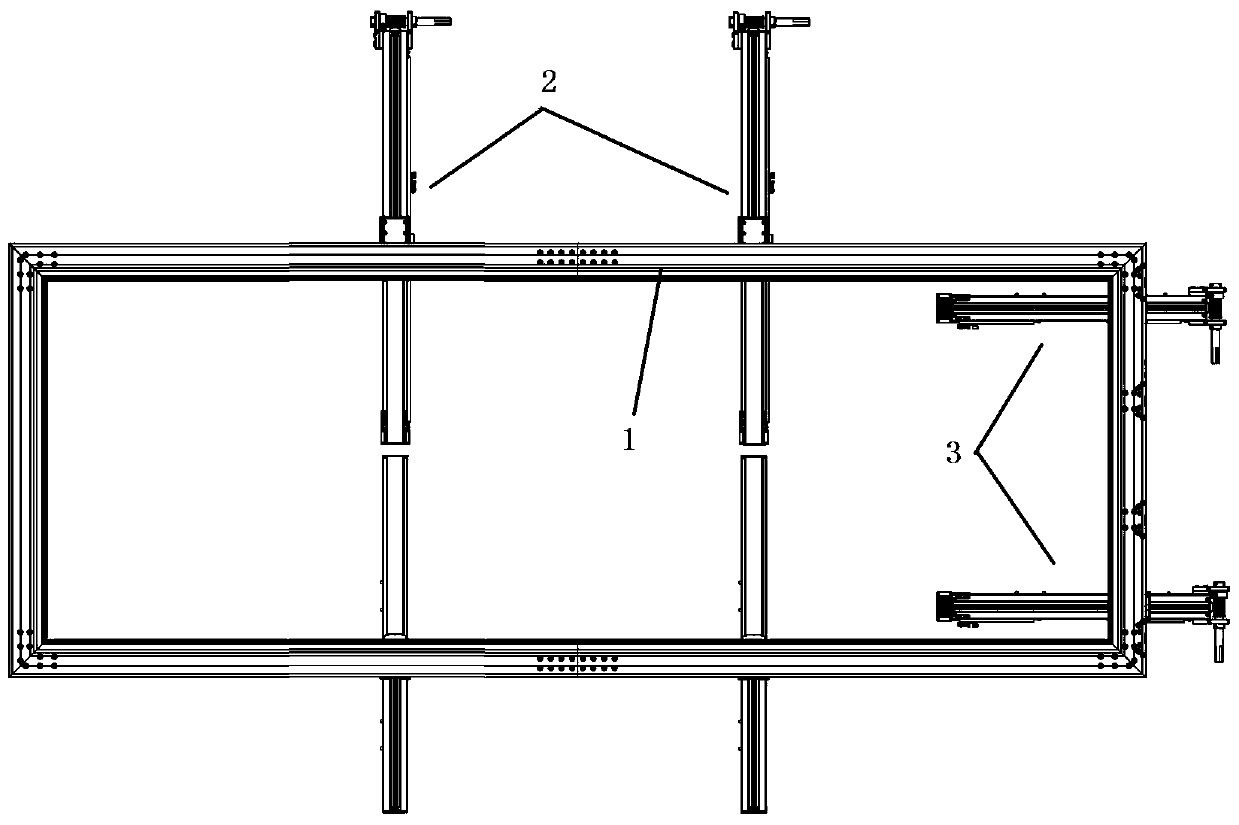
[0040] Such as figure 1 , figure 2 As shown, this embodiment provides a suspended embroidery frame device for a computerized embroidery machine, including:

[0041] The frame 1 includes four side frames that are connected end to end to form a rectangle in turn. The lower surface of the longer side frame extends along its length extension direction to provide a groove 11 with an opening downward. Two of the grooves 11 The longer sides are provided with a protruding portion 12 protruding to the center of the groove 11 with a circular arc surface, and the length extension direction of the protrusion 12 is consistent with the length extension direction of the longer side of the groove 11; wherein The longer side frame is the side frame with a relatively longer length among the four side frames of the frame 1. According to the situation in the prior art, the length of the side frame extending along the X stroke direction of the frame 1 will be longer than that along the Y stroke ...

Embodiment 2

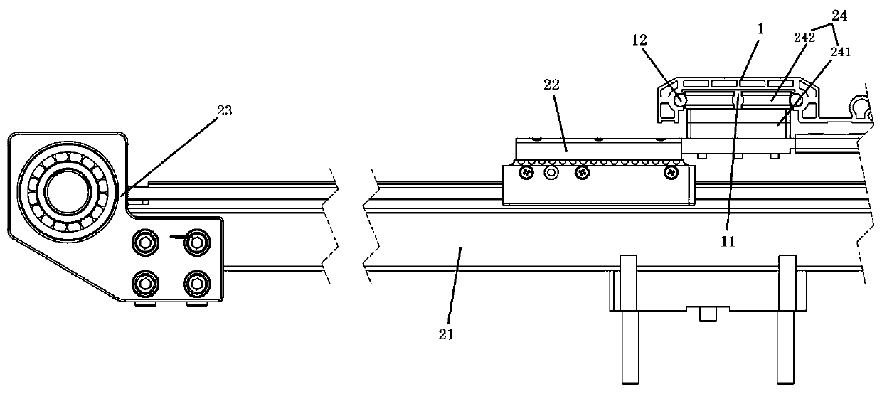
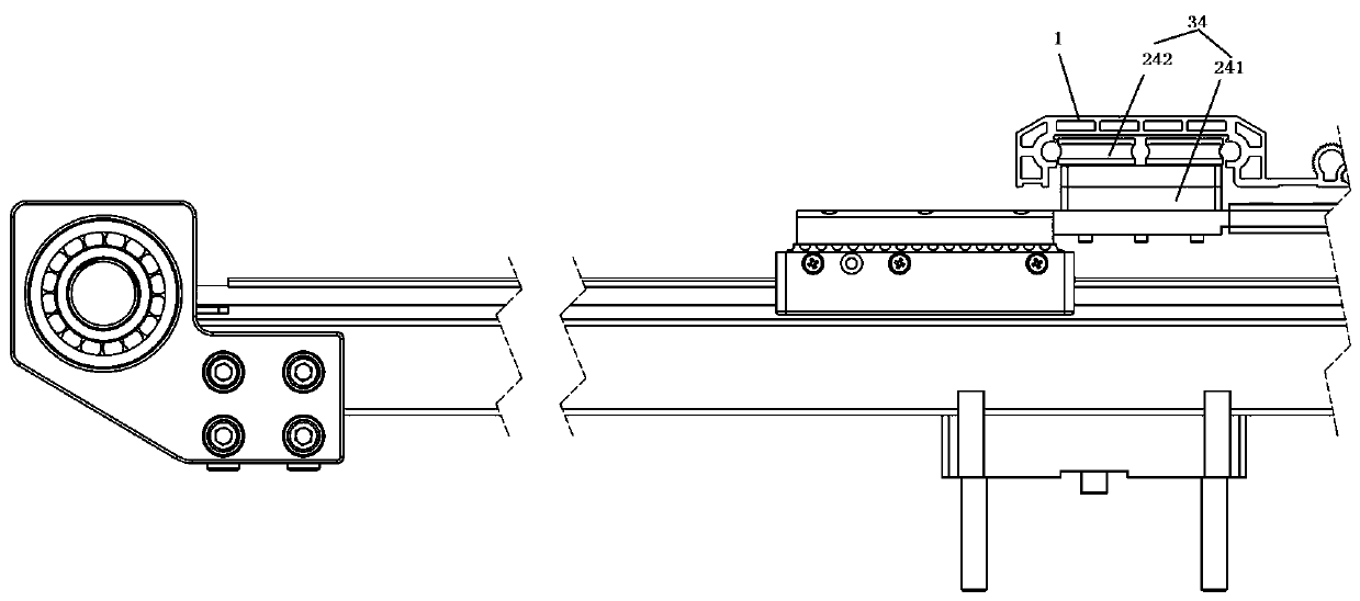
[0049] Such as image 3 As shown, the difference between this embodiment and the previous embodiments is that the lower surface of the shorter side frame in this embodiment extends along its length extension direction to provide a groove 11 with an opening downward, and the groove 11 Both longer sides are provided with a protruding portion 12 protruding to the center of the groove 11 with a circular arc surface, and the length extension direction of the protrusion 12 is consistent with the length extension direction of the longer side of the groove 11 , the X-frame connection assembly 34 includes a connection seat 241 connected to the upper surface of the X driving trolley and a U-shaped bearing 242 horizontally connected to the upper surface of the connection seat 241, and the outer peripheral surface of the U-shaped bearing 242 is recessed and the protruding arc surface of the protruding part 12, and there are at least two U-shaped bearings 242, which are respectively connec...

Embodiment 3

[0052] Such as Figure 4 , Figure 5As shown, the difference between this embodiment and Embodiment 1 is that the X-frame connection assembly 34 in this embodiment includes a Y-direction auxiliary rail 341, several bearing connection parts 342 and a trolley connection part 343, and the Y-direction auxiliary rail 341 is parallel to the shorter side frame and is connected to the shorter side frame through the bearing connecting parts 342 arranged at intervals along the length extension direction of the shorter side frame, and the Y-direction auxiliary rail 341 is lowered The surface is connected to the upper surface of the X driving trolley through the trolley connecting portion 343, specifically, the lower surface of the Y-direction auxiliary rail 341 that is relatively far away from the side of the shorter side frame is connected to the upper surface of the X driving trolley through the trolley connecting portion 343. The upper surface of the X drive trolley is connected, and...


PUM


Abstract

The invention discloses a suspension embroidery frame device of a computerized embroidery machine; the suspension embroidery frame device comprises: a frame, wherein a groove is formed in the lower surface of each framing member of the frame and extended along the length direction of the framing member, and each of two longer side surfaces of each groove is provided with a protruding part having acircular arc surface protruded towards the center of the groove; a Y-direction driving assembly, comprising a Y driving guide rail, a Y driving trolley, a Y transmission assembly and a Y frame connecting assembly, wherein the Y transmission assembly is connected with the Y driving guide rail and used for driving the Y driving trolley to slide along the Y driving guide rail, the Y frame connectingassembly comprises a connecting seat connected to the upper surface of the Y driving trolley and a U-shaped bearing connected to the connecting seat, and the concave part of the outer peripheral surface of the U-shaped bearing abuts against the arc surface protruding from the protruding part; and an X-direction driving assembly, comprising an X driving guide rail, an X driving trolley, an X transmission assembly and an X frame connecting assembly arranged on the X driving trolley and connected with the frame. The suspension embroidery frame device has the advantages of good disassembly and assembly convenience, no friction with a bedplate, low wear rate, good integral driving property and good operation reliability.

Description

technical field [0001] The invention relates to the technical field of embroidery machines, in particular to a suspended embroidery frame device for a computerized embroidery machine. Background technique [0002] The stability of computerized embroidery machine frame is a key factor affecting the quality of embroidery machine embroidery. Precise control of embroidery machine frame can greatly improve the quality of embroidery, reduce the rate of embroidery machine breakage, and improve production efficiency. At present, the existing embroidery machine frame has many forms: one is the traditional embroidery frame, which is pasted on the platen plane by felt. This method has the following defects: 1. Due to the friction between the embroidery frame and the platen plane If the embroidery frame exists, it will cause unstable operation of the embroidery frame on the plane. In the case of high embroidery quality, this method will not be fully realized; 2. Due to the long-term fri...

Claims


Application Information

Patent Timeline
Patent Type & Authority Applications(China)
IPC IPC(8): D05C9/04D05C9/14
CPCD05C9/04D05C9/14
Inventor 陈天池陈天龙张汉苗郑邓飞楼凯
Owner ZHEJIANG YUELONG SEWING EQUIP
Why Eureka
Try Eureka