
Method for testing direct-current magnetic field intensity

A technology of magnetic field strength and DC magnetic field, applied in the size/direction of magnetic field, measuring device, measuring resonant frequency, etc., can solve the problems of long response time, quantification error of digital frequency meter reading, influence of water diamagnetic susceptibility, etc. Achieve the effect of eliminating interference and attenuation, good frequency stability, and accurate testing

Active Publication Date: 2019-12-31
NINGBO UNIV
View PDF5 Cites 4 Cited by
  • Summary
  • Abstract
  • Description
  • Claims
  • Application Information

AI Technical Summary

Problems solved by technology

Among these methods, the Hall element detection method has the advantages of small size, simple structure, wide frequency response, large output voltage change, and long life, but the interchangeability is poor, and the measurement circuit will cause heat if the working time of the measurement circuit is too long, making the Hall element The Hall voltmeter in the circuit system produces measurement errors and unequal potentials caused by incompletely symmetrical electrode positions
The flow-type NMR field meter needs to use a strong magnetic field to pre-polarize the flowing water sample, which will be very difficult to detect a weak magnetic field, and there will also be accuracy problems, such as the quantification error of the digital frequency meter reading, the diamagnetic magnetization of water Rate Effects and Detector Noise Effects
Reed switch magnetic field detection structure is simple, small size, easy to control, but the response time is long
The fluxgate magnetometer has high sensitivity and is easy to carry, but the circuit is complex, the circuit parameters are greatly affected by temperature and difficult to debug

Method used


Image

  • Method for testing direct-current magnetic field intensity
  • Method for testing direct-current magnetic field intensity
  • Method for testing direct-current magnetic field intensity

Examples


Embodiment Construction

[0022] The present invention will be further described in detail below in conjunction with the accompanying drawings and embodiments.

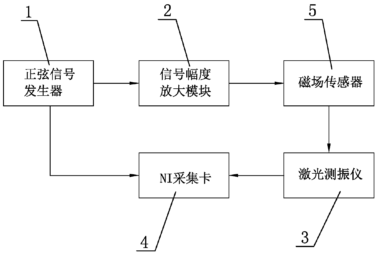
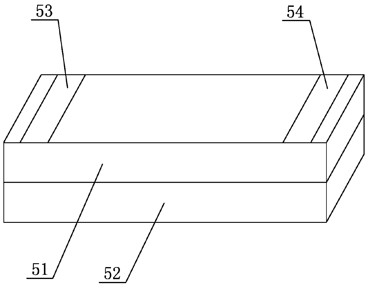
[0023] As shown in the figure, a test method for DC magnetic field strength, the test system used includes a sinusoidal signal generator 1, a signal amplitude amplification module 2, a laser vibrometer 3, an NI acquisition card 4, and a magnetic field sensor excited by a transverse field 5. The magnetic field sensor 5 includes a piezoelectric material layer 51 and a piezoelectric material layer 52 bonded and fixed to each other. A positive electrode 53 and a negative electrode 54 are arranged on one surface of the piezoelectric material layer 51, where the positive electrode 53 and the negative electrode 54 are located. The surface of the piezoelectric material layer 51 and the bonding surface of the piezoelectric material layer 52 are opposite to each other, so as to realize the transverse field excitation of the magnetic field sensor 5, and t...


PUM


Abstract

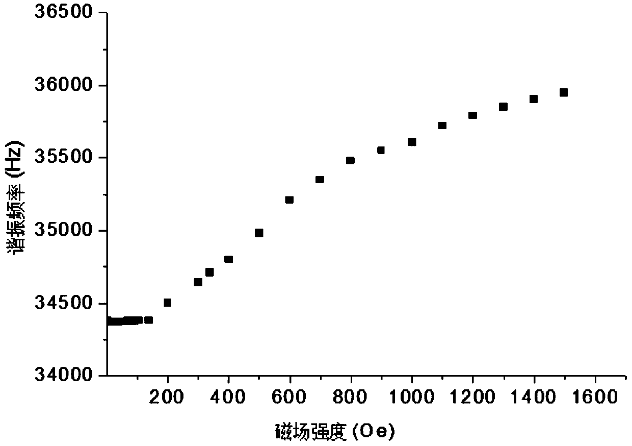
The invention discloses a method for testing the direct-current magnetic field intensity. A sinusoidal signal generator, a signal amplitude amplification module, a laser vibration meter, an NI acquisition card and a transverse-field-excited magnetic field sensor are arranged. The method has the following advantages: the direct-current magnetic field intensity is determined based on the resonant frequency of the magnetic field sensor under the transverse field excitation, so that the influence of the temperature on the magnetic field sensor is eliminated; the direct-current magnetic field in different intensity ranges is determined based on resonant frequencies of the magnetic field sensor in three different vibration modes, so that the direct-current magnetic field intensity is accuratelytested; and since the positive electrode and the negative electrode on the magnetic field sensor are arranged at the same side of the piezoelectric material layer, all electrodes and leads are arranged at the rear end of the magnetic field sensor, so that the interference and attenuation of the electrode to magnetic field detection signal are eliminated and the accuracy of magnetic field intensitytesting is further ensured.

Description

technical field [0001] The invention relates to the test of magnetic field parameters, in particular to a test method for DC magnetic field strength. Background technique [0002] At present, the measurement methods of DC magnetic field mainly include Hall element detection method, flowing water NMR measurement field method, reed switch magnetic field detection method, fluxgate magnetometer method and so on. Among these methods, the Hall element detection method has the advantages of small size, simple structure, wide frequency response, large output voltage change, and long life, but the interchangeability is poor, and the measurement circuit will cause heat if the working time of the measurement circuit is too long, making the Hall element The Hall voltmeter in the circuit system produces measurement errors and unequal potentials caused by incomplete symmetry of electrode positions. The flow-type NMR field meter needs to use a strong magnetic field to pre-polarize the flo...

Claims


Application Information

Patent Timeline
IPC IPC(8): G01R33/02G01H13/00G01H9/00
CPCG01H9/00G01H13/00G01R33/02
Inventor 杜建科丁雪丁本杰金育安张明华李光勇娄佳华李成
Owner NINGBO UNIV
Learn More