
Heating type electromagnetic rivet-free connecting device and working method

A connecting device and rivetless technology, which is applied in the direction of metal processing equipment, forming tools, manufacturing tools, etc., can solve the problem of unsatisfactory performance of connecting joints in the forming effect, limited room for improving the performance of connecting joints, and difficulty in one-time stamping and forming, etc. Problems, achieve the effect of shortening the forming time, simple structure and convenient operation

Pending Publication Date: 2020-01-03
FUZHOU UNIV
View PDF0 Cites 4 Cited by
  • Summary
  • Abstract
  • Description
  • Claims
  • Application Information

AI Technical Summary

Problems solved by technology

[0004] Rivetless connection requires a large amount of forming force in the stamping process. The existing rivetless connection equipment mainly focuses on the adjustment of the structure of the rivetless connection device, but the power source still mainly uses traditional hydraulic pressure and air pressure, so that riveting and forming The space for improving the performance of the post-connection joint is limited, and the rivetless connection improvement scheme for some materials with high deformation resistance and poor joint performance after forming is limited. The forming process has certain limitations, and it is difficult to achieve one-time stamping forming
Due to the use of the cold deformation ability of the plate itself, the plate is locally deformed and the mechanical connection of the plate is connected together, resulting in the forming effect and the performance of the connection joint are not ideal, and cracks are easy to occur on the plate.

Method used


Image

  • Heating type electromagnetic rivet-free connecting device and working method
  • Heating type electromagnetic rivet-free connecting device and working method
  • Heating type electromagnetic rivet-free connecting device and working method

Examples


Embodiment Construction

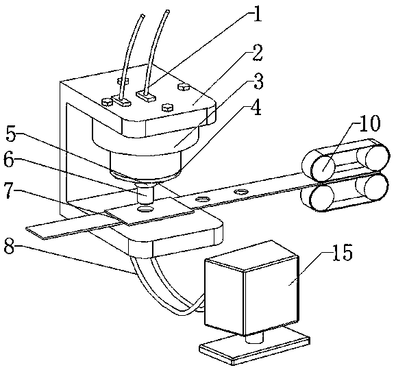
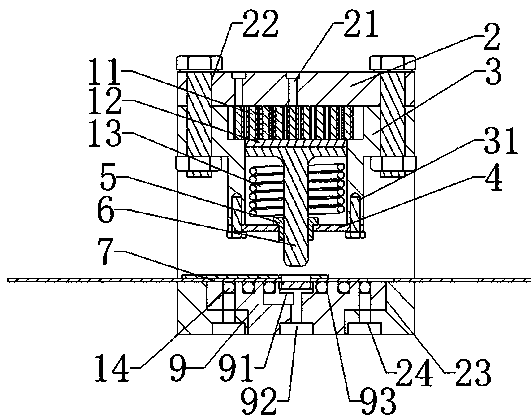
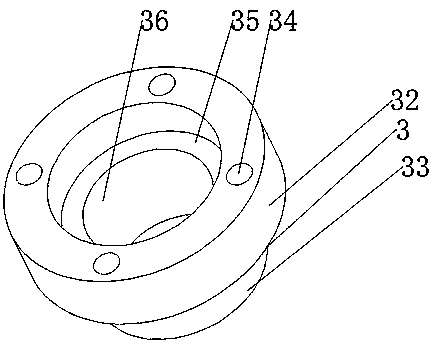
[0063] Such as Figure 1-15 As shown, a heating type electromagnetic rivetless connection device, the connection device includes a fixed frame 2; the upper part of the fixed frame is provided with a punch driving device, and the lower part is provided with a riveting die 9; the riveting die is provided with an eddy current The effect is the induction heating coil 14 for heating the workpiece to be connected; the punch driving device includes an electromagnetic induction coil 11 and a driver 12 with a metal structure connected to the punch 6; the electromagnetic induction coil is close to or connected to the metal structure of the driver , when the electromagnetic induction coil is working, the alternating magnetic field formed by its electrification induces an induced current forming a mutually repulsive magnetic field at the metal structure of the driver, and the electromagnetic induction coil pushes the driver downward with electromagnetic repulsion, driving the punch to impa...


PUM


Abstract

The invention provides a heating type electromagnetic rivet-free connecting device and a working method. The connecting device comprises a fixed frame. A puncher pin drive device is arranged on the upper portion of the fixed frame, and a rivet mold is arranged on the lower portion of the fixed frame. An induction heating coil capable of heating to-be-connected workpieces through the eddy current effect is arranged on the rivet mold. The puncher pin drive device comprises an electromagnetic induction coil and a driver connected with a puncher pin and provided with a metal structure. The electromagnetic induction coil is adjacent to or connected with the metal structure of the driver. When the electromagnetic induction coil works, the induced current capable of forming a mutual exclusion magnetic field is induced by an alternating magnetic field formed by powering on the electromagnetic induction coil on the metal structure of the driver, the electromagnetic induction coil pushes the driver to move downwards through electromagnetic repulsive force, and the puncher pin is driven to impact on the two heated to-be-connected metal workpieces on the rivet mold so that the to-be-connectedmetal workpieces can be connected. Through the principle of electromagnetic induction heating, preheating of two kinds of to-be-connected metal is achieved, electromagnetic force is used as drive forso that the two kinds of to-be-connected metal workpieces can generate deformation to achieve one-time punching forming, and the forming effect is improved.

Description

technical field [0001] The invention relates to the technical field of electrothermal processing, in particular to a heating type electromagnetic rivetless connection device and a working method. Background technique [0002] The manufacturing capacity of automobiles is an important manifestation of a country's comprehensive national strength. In recent years, my country's automobile industry has developed rapidly, and its current production and sales have surpassed that of the United States, ranking first in the world. Reducing the weight of automobile bodies is an effective way to improve automobile economy. Research shows that when the weight of the vehicle is reduced by 10%, the fuel economy is increased by 3.8%, the acceleration time is reduced by 8%, the CO2 emission is reduced by 4.5%, the braking distance is reduced by 5%, the tire life is increased by 7%, and the steering force is reduced by 6%. . The key to realize the lightweight of the car is to use a large num...

Claims


Application Information

Patent Timeline
Patent Type & Authority Applications(China)
IPC IPC(8): B21D39/02B21D37/16
CPCB21D39/026B21D37/16
Inventor 邓将华黄顺强范治松解梦琪钟学聪
Owner FUZHOU UNIV
Learn More