Clamping equipment with anti-skid grain engraving for pincers machining

A technology for anti-skid texture and clamping equipment, applied in metal processing equipment, manufacturing tools, metal processing machinery parts, etc., can solve the problems of non-skid texture engraving failure, inability to move left and right, limited fixing effect, etc., to reduce friction coefficient, convenient Engraving, guaranteeing the effect of rationality

Inactive Publication Date: 2020-01-03
DONGGUAN KAILEDI NUMERICAL CONTROL SCI & TECH CO LTD
View PDF0 Cites 3 Cited by
  • Summary
  • Abstract
  • Description
  • Claims
  • Application Information

AI Technical Summary

Problems solved by technology

[0004] The object of the present invention is to provide a clamping device with anti-slip pattern engraving for pliers processing, so as to solve the problem that the existing clamping devices proposed in the above background technology often use suspension to clamp and fix the pliers during use. Limited, when the pressure generated during engraving is applied to the upper end, the pliers may shift, resulting in the failure of anti-slip texture engraving, and the clamping equipment is mostly fixed installation, which cannot effectively move left and right according to your own needs.

Method used


Image

  • Clamping equipment with anti-skid grain engraving for pincers machining
  • Clamping equipment with anti-skid grain engraving for pincers machining
  • Clamping equipment with anti-skid grain engraving for pincers machining

Examples


Embodiment Construction

[0026] The technical solutions in the embodiments of the present invention will be clearly and completely described below in conjunction with the accompanying drawings in the embodiments of the present invention. Obviously, the described embodiments are only some of the embodiments of the present invention, not all of them. Based on The embodiments of the present invention and all other embodiments obtained by persons of ordinary skill in the art without making creative efforts belong to the protection scope of the present invention.

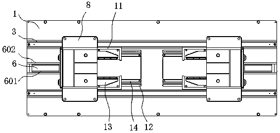
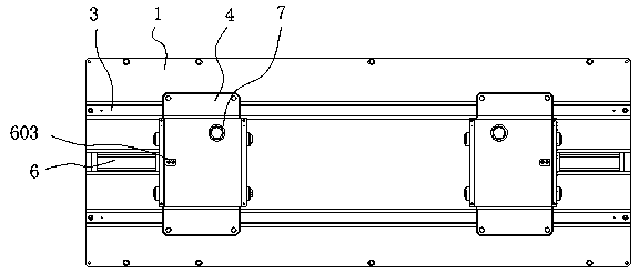
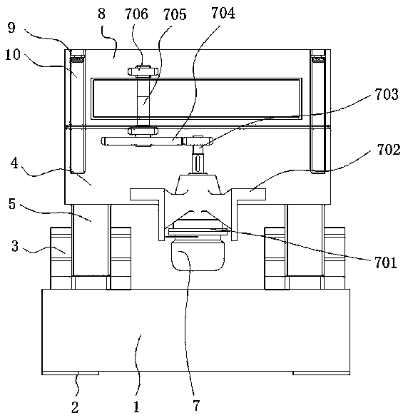
[0027] see Figure 1-5 , the present invention provides a technical solution: a clamping device with anti-slip pattern engraving for pliers processing, including a base 1, an anti-slip pad 2, a slide rail 3, a lower bearing platform 4, a slider 5, a pulling structure 6, and a hydraulic rod 601, side splint 602, fixed head 603, transmission structure 7, motor 701, bracket 702, rotating shaft 703, reduction gear set 704, connecting shaft 705, bear...


PUM


Abstract

The invention relates to clamping equipment with anti-skid grain engraving for pliers machining. The clamping equipment comprises a base and lower bearing platforms, wherein anti-skid pads are fixed to the periphery of the bottom of the lower end of the base, sliding rails are welded to two sides of the upper end of the base, the lower bearing platforms are movably connected to the tops of the sliding rails, sliding blocks are welded at the joints between the lower bearing platforms and the sliding rails, pulling structures are fixed at the rear ends of the lower bearing platforms, transmission structures are arranged in the middles of the lower bearing platforms, the tops of the lower bearing platforms are provided with upper bearing platforms, and open holes are formed in the peripheriesof the interiors of the upper bearing platforms. According to the clamping equipment, clamping structures are arranged, the clamping structures are provided with lower die platforms, the sizes of thelower die platforms are mutually matched with formed hole grooves and the size shape of pliers so that the lower die platforms can exert effective supporting force on the pliers, meanwhile, detachable structures are adopted between embedded blocks on the two sides of the lower die platforms and mounting platforms, then a user can effectively disassemble the lower die platforms according to the use requirements of the user, and the use by the user is facilitated.

Description

technical field [0001] The invention relates to the technical field of pliers processing, in particular to a clamping device with anti-slip pattern engraving for pliers processing. Background technique [0002] Pliers are a hand tool used to clamp and fix workpieces or twist, bend, and cut metal wires. The shape of the pliers is V-shaped, and it usually includes three parts: handle, pliers jaw and pliers mouth. Pliers are generally made of carbon For the manufacture of structural steel, it is first forged, pressed and rolled into the shape of the pliers blank, then it is processed by metal cutting such as grinding and polishing, and finally it is heat treated. It has a high degree of aesthetics, and at the same time, the pliers need to be clamped during processing to ensure stable carving. [0003] Existing clamping equipment mostly adopts suspension to clamp and fix the pliers during use. The fixing effect is limited. When the pressure generated during engraving is applied...

Claims


Application Information

Patent Timeline
Patent Type & Authority Applications(China)
IPC IPC(8): B23Q3/06B23Q1/25B25H1/08B25H1/10
CPCB23Q1/25B23Q3/062B25H1/08B25H1/10
Inventor 邓玲凤陈马鑫
Owner DONGGUAN KAILEDI NUMERICAL CONTROL SCI & TECH CO LTD
Why Eureka
Try Eureka