Automatic machining machine tool transmission mechanism of metal plate shell

A technology for processing machine tools and transmission mechanisms, which is applied in the direction of metal processing machinery parts, metal processing, metal processing equipment, etc., can solve the problems of conveyor belt shaking, damage to elastic plates and movable pressure bars, and reduce the service life of conveyor belts. The method is simple, the effect of avoiding position deviation and reducing the error rate

Inactive Publication Date: 2020-01-03
CHANGXING FEIXIANG SHEET METAL TECH CO LTD
View PDF8 Cites 3 Cited by
  • Summary
  • Abstract
  • Description
  • Claims
  • Application Information

AI Technical Summary

Problems solved by technology

[0003] However, this patent has the following disadvantages. The motor rotates to drive the movable pressure rod to press down the knocking device, which will cause great damage to the elastic plate and the movable pressure rod. It will cause the position of the conveyor belt to shift, which will affect the normal processing of the machine tool and reduce the service life of the conveyor belt

Method used


Image

  • Automatic machining machine tool transmission mechanism of metal plate shell
  • Automatic machining machine tool transmission mechanism of metal plate shell
  • Automatic machining machine tool transmission mechanism of metal plate shell

Examples


Embodiment Construction

[0024] The preferred embodiments of the present invention will be described below in conjunction with the accompanying drawings. It should be understood that the preferred embodiments described here are only used to illustrate and explain the present invention, and are not intended to limit the present invention.

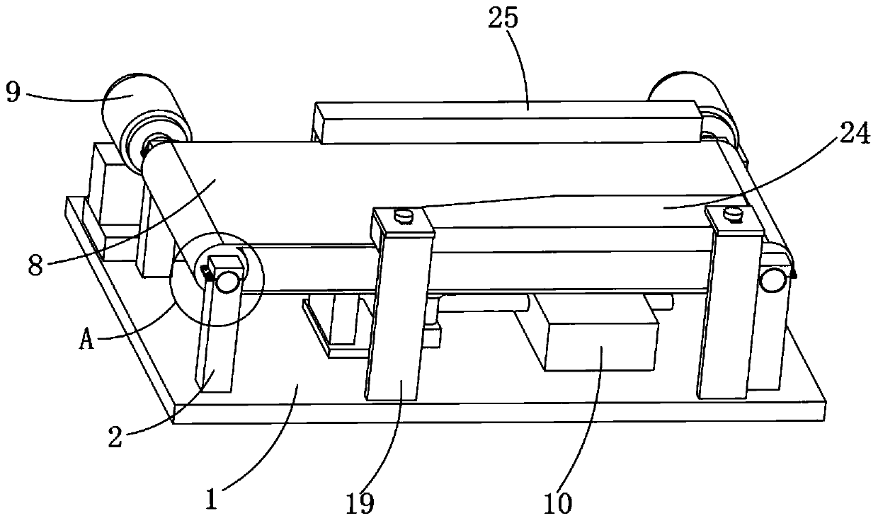
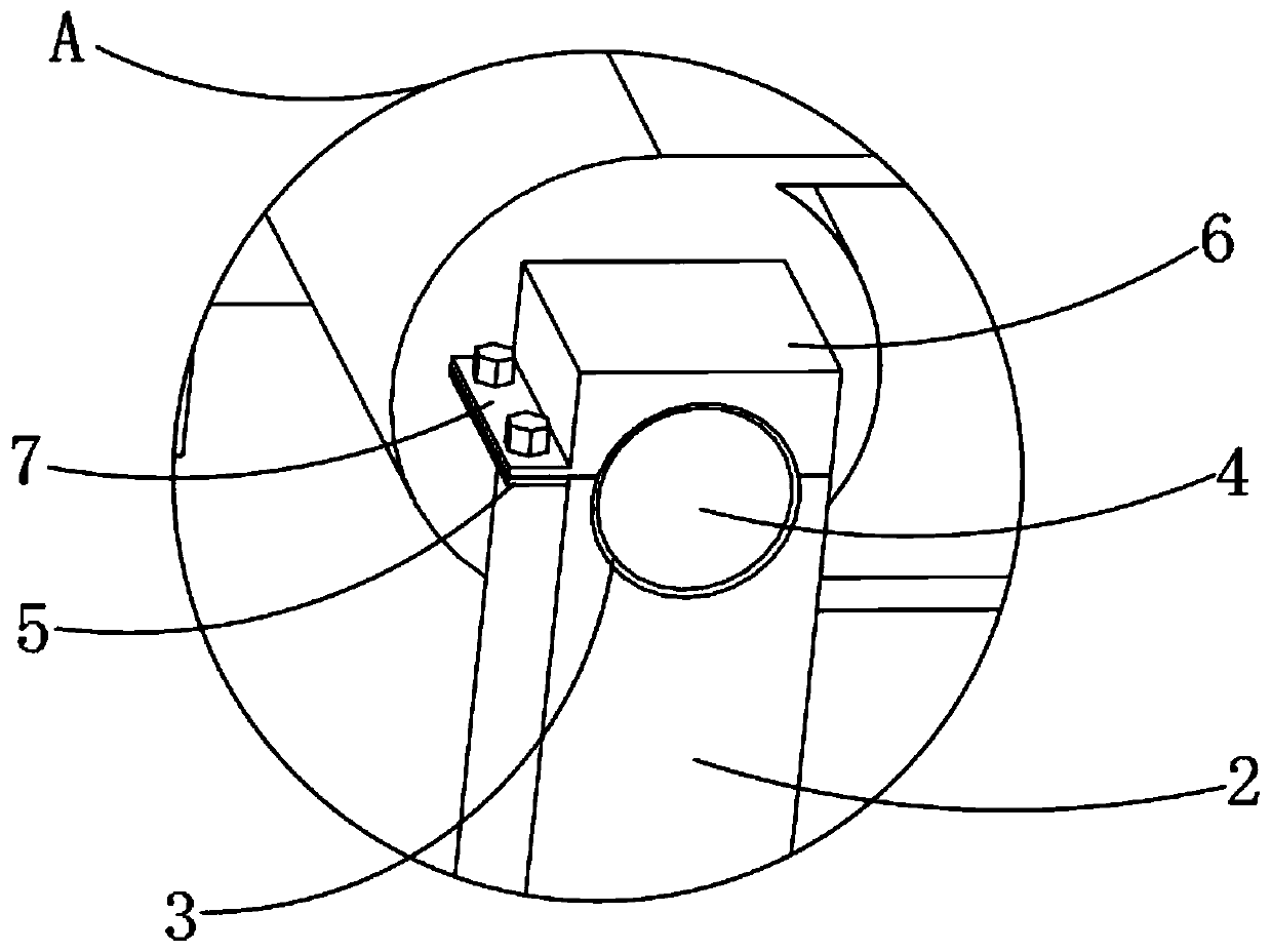
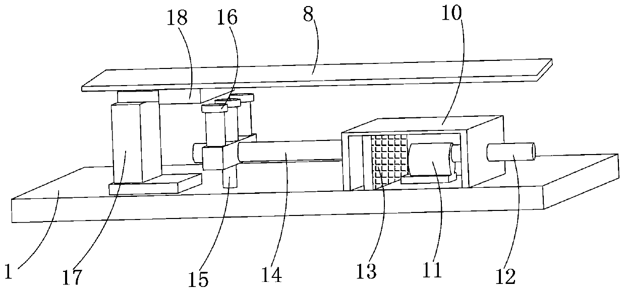
[0025] Example: such as Figure 1-4 As shown, the present invention provides a technical solution, an automatic processing machine tool transmission mechanism for a sheet metal shell, a first support frame 2 is symmetrically installed at the four corners of the top of the base 1, and the top of the first support frame 2 One end is connected with a bump 5, and the top of the first support frame 2 is provided with a groove 3, and a roller 4 is installed inside the groove 3, the number of the roller 4 is two, and one end of the roller 4 is installed in the groove 3, the other end of the roller 4 extends into the corresponding other groove 3 and is connected with the mo...


PUM


Abstract

The invention discloses an automatic machining machine tool transmission mechanism of a metal plate shell. First supporting frames are symmetrically mounted on the four corners of the top of a base, convex blocks are connected to one ends of the tops of the first supporting frames, grooves are formed in the tops of the first supporting frames, rolling shafts are arranged in the grooves, a conveying belt is arranged on the surfaces of the rolling shafts, one ends of the rolling shafts are connected with motors, a collection box is arranged at the position, below the conveying belt, of the top of the base, a fan is arranged in the collection box, one end of the fan is connected with a discharging pipe, one end of the collection box is connected with a guide pipe, one end of the guide pipe isconnected with a dust suction pipe, and the top of the support is connected with a cleaning brush. Through the cleaning brush and the dust suction pipe, dust stained on the conveying belt is removed,the phenomenon that dust falling on the surface of the conveying belt during machining is flied off to the other places is avoided, the cleanliness of the machining environment is ensured, the cleaning brush and the dust suction pipe can be more directly treated, and the side effect on a machine tool is avoided.

Description

technical field [0001] The invention relates to the technical field of transmission devices, in particular to a transmission mechanism for an automatic processing machine tool for sheet metal shells. Background technique [0002] Conveyor belt, also known as conveyor belt, is a rubber, fiber and metal composite product used to carry and transport materials in belt conveyor belts. Conveyor belts are widely used in cement, coking, metallurgy, chemical and steel industries with short conveying distances For occasions with small conveying volume, the conveyor belt is safe to operate, easy to use, easy to maintain, low in freight, and can shorten the transportation distance, reduce the engineering cost and save manpower and material resources. For this reason, the Chinese patent discloses an automatic machine tool material transmission device, application number It is 201821663110.6, the patent uses the vibration device arranged on the U-shaped base and the dust suction pipe on t...

Claims


Application Information

Patent Timeline
Patent Type & Authority Applications(China)
IPC IPC(8): B23Q7/00B23Q11/00
CPCB23Q7/00B23Q11/0046
Inventor 李应昌段博
Owner CHANGXING FEIXIANG SHEET METAL TECH CO LTD
Why Eureka
Try Eureka