Supercharge Your Innovation With Domain-Expert AI Agents!

Aerostatic Bearing Based on Passive Vibration and Energy Dissipation Based on Additional Mass Motion

A technology of additional mass and gas static pressure, applied in the direction of air cushion bearings, bearings, shafts and bearings, etc., can solve the problems of small bearing capacity, increase the internal air cavity of the air bearing, and increase the risk of nonlinear instability of fluid motion, etc., to achieve The effect of large bearing capacity and simple structure

Active Publication Date: 2021-06-29
SHANGHAI SATELLITE ENG INST
View PDF10 Cites 0 Cited by
  • Summary
  • Abstract
  • Description
  • Claims
  • Application Information

AI Technical Summary

Problems solved by technology

Significantly reduces the damage of external vibration and shock to the static and dynamic performance of the bearing system, and the processing is simple, but this technology significantly increases the internal air cavity of the air bearing, resulting in the reduction of the stiffness of the air bearing and other problems
The double-layer air bearing mentioned in the patent CN104533954A, through the multi-level air bearing, significantly increases the bearing capacity and stiffness of the air bearing, but it will bring a significant increase in installation difficulty, and at the same time, the nonlinear loss of fluid motion issues such as increased risk
Patent CN200999795Y mentions an elastically deformable air bearing. Only the annular plane around the concave spherical surface on the working surface has a small area of ​​contact with the guide rail surface, and at the same time, the compressed air can easily fill the air cavity of the concave core to ensure the working stability. However, this technology Insufficient bearing capacity

Method used


Image

  • Aerostatic Bearing Based on Passive Vibration and Energy Dissipation Based on Additional Mass Motion
  • Aerostatic Bearing Based on Passive Vibration and Energy Dissipation Based on Additional Mass Motion
  • Aerostatic Bearing Based on Passive Vibration and Energy Dissipation Based on Additional Mass Motion

Examples


specific Embodiment approach 1

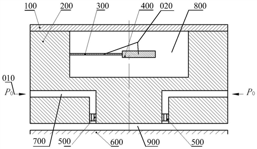
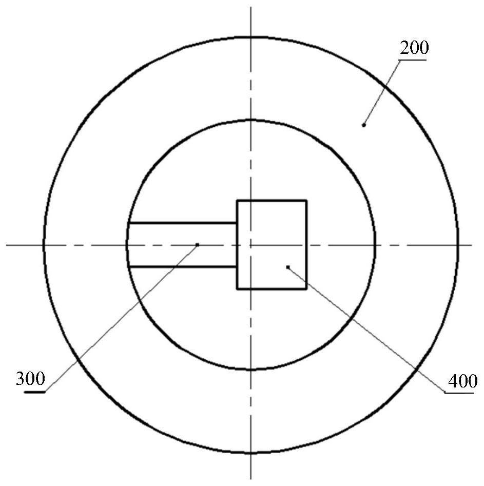
[0048] Gas static pressure bearings based on passive vibration and energy consumption based on the motion of additional mass, such as figure 1 and figure 2 As shown, it is composed of the bearing body 200, the throttle plug 500 and the cladding plate 100. The compressed air 010 passes through the throttle plug 500 arranged in the bearing body 200 at P0 pressure and enters the gap between the bearing body 200 and the bearing corresponding surface 600 900, and form a thin air film, through which the suspension support of the bearing main body 200 is realized; a flexible thin plate 300 and an additional mass 400 are arranged on the inner wall of the upper cavity 800 of the bearing main body 200, and one side of the flexible thin plate 300 is tightly connected with the The bearing body 200 is fastened to the additional mass 400 on the other side; during the operation of the bearing, the additional mass 400 can move in a vertical direction relative to the bearing body 200 through ...

specific Embodiment approach 2

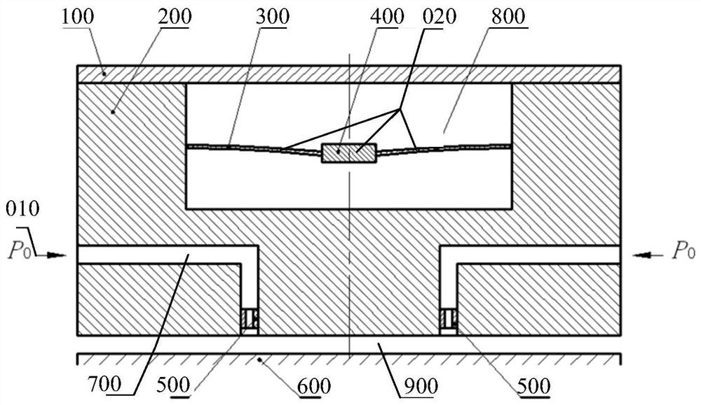
[0052] Gas static pressure bearings based on passive vibration and energy consumption based on the motion of additional mass, such as image 3 As shown, it is composed of the bearing body 200, the throttle plug 500 and the cladding plate 100. The compressed air 010 passes through the throttle plug 500 arranged in the bearing body 200 at P0 pressure and enters the gap between the bearing body 200 and the bearing corresponding surface 600 900, and a thin air film is formed, and the suspension support of the bearing body 200 is realized by the thin air film; two flexible thin plates 300 and an additional mass 400 are arranged on the inner wall of the upper cavity 800 of the bearing body 200, and the two flexible thin plates 300 are one One side is fastened to the bearing body 200, and the other side is fastened to the two sides of the additional mass 400. The two flexible thin plates 300 are symmetrical to the additional mass 400. During the operation of the bearing, the additiona...

specific Embodiment approach 3

[0054] Gas static pressure bearings based on passive vibration and energy consumption based on the motion of additional mass, such as Figure 4 As shown, it is composed of the bearing body 200, the throttle plug 500 and the cladding plate 100. The compressed air 010 passes through the throttle plug 500 arranged in the bearing body 200 at P0 pressure and enters the gap between the bearing body 200 and the bearing corresponding surface 600 , and a thin air film is formed, and the suspension support of the bearing body 200 is realized by the thin air film; a flexible spring 300 and an additional mass 400 are arranged at the bottom of the upper cavity 800 of the bearing body 200, and one side of the flexible spring 300 is tightly connected with the bearing body 200, and the other side is fastened to the additional mass 400; the additional mass 400 can move in a vertical direction relative to the bearing body 200 through the flexible spring 300; when the aerostatic bearing vibrates ...


PUM


Abstract

The invention belongs to the field of spacecraft physics simulation. The invention provides an aerostatic bearing based on passively induced vibration and energy consumption of additional mass motion. When the aerostatic bearing vibrates axially, it is driven to be connected to the bearing main body (200). One end of the flexible thin plate (300) on the cavity wall generates axial vibration at the same frequency at the same time, and the additional mass (400) fastened to the other end of the flexible thin plate (300) lags behind the bearing main body (200) through the flexible thin plate (300). Passive axial vibration of different frequencies, the energy generated by the vibration of the bearing main body (200) is dissipated through the passive vibration of the additional mass (400), so as to realize the vibration suppression of the gas hydrostatic bearing, without changing the bearing capacity The gas static pressure bearing has the advantages of high stability, simple structure, large load capacity, etc., and can be used in the applicable occasions of large load capacity and high stability gas static pressure bearing.

Description

technical field [0001] The invention relates to the field of physical simulation of spacecraft, and in particular, to a gas-static bearing with passive vibration-induced energy consumption based on motion of additional mass. Background technique [0002] Aerostatic bearings are widely used in spacecraft micro-low gravity environment simulation, ultra-precision machining and measuring equipment, medical testing equipment and other fields due to their high motion accuracy, high motion speed and non-contact working characteristics. Due to the high compressibility of gas, it is difficult to take into account the bearing capacity, stiffness and stability of aerostatic bearings, which has become a key technical difficulty restricting the development of aerostatic bearing technology and engineering applications. With the continuous improvement of motion accuracy and motion speed requirements in precision and ultra-precision equipment, the motion characteristics of gas turbulence br...

Claims


Application Information

Patent Timeline
Patent Type & Authority Patents(China)
IPC IPC(8): F16C32/06
CPCF16C32/0614F16C32/0622
Inventor 马伟徐毅廖波许域菲谢进进孙杰
Owner SHANGHAI SATELLITE ENG INST
Features
  • R&D
  • Intellectual Property
  • Life Sciences
  • Materials
  • Tech Scout
  • Unparalleled Data Quality
  • Higher Quality Content
  • 60% Fewer Hallucinations
Learn More