
Burner facility for biomass boiler combustion system

A technology for biomass boilers and combustion systems, which is applied to burners, burners, and combustion equipment for burning powder fuels, and can solve problems such as material blockage and environmental damage

Active Publication Date: 2021-04-09
陕西分布式能源股份有限公司
View PDF6 Cites 0 Cited by
  • Summary
  • Abstract
  • Description
  • Claims
  • Application Information

AI Technical Summary

Problems solved by technology

[0006] To sum up, the present invention provides a burner facility for a biomass boiler combustion system. Through structural and functional improvements, the existing biomass particle burner is solved. When burning, due to the small size of the particle itself , if the blown air is large, it will cause the fly ash to be discharged into the air with the air flow, causing environmental damage, and the existing biomass burning device is a continuous feeding combustion method. If it cannot be fully burned, it will cause material clogging problem

Method used

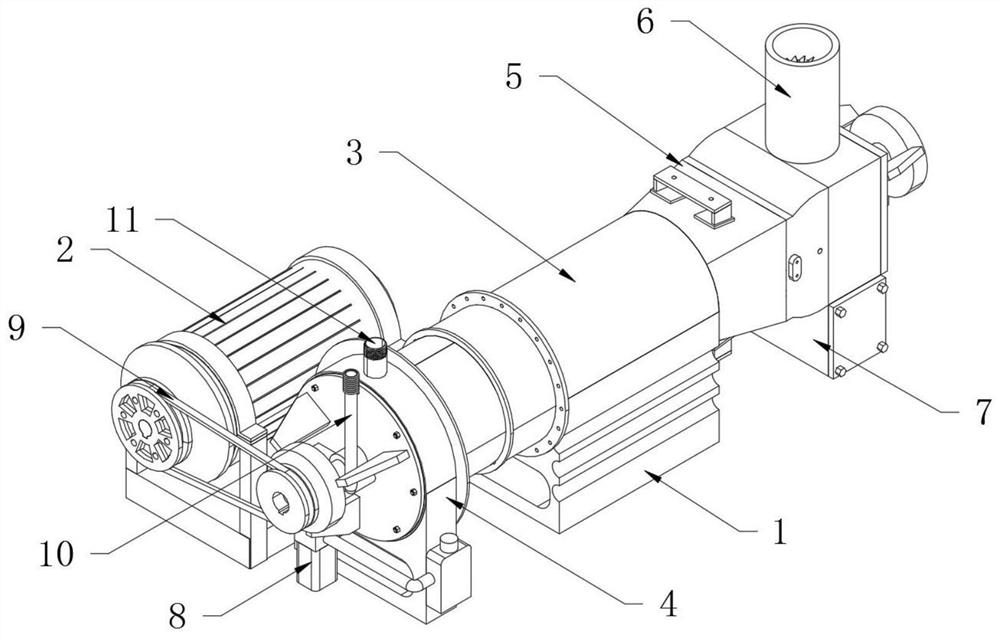
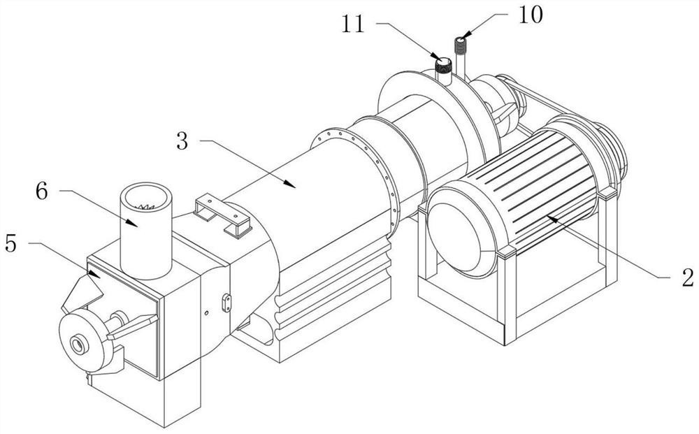
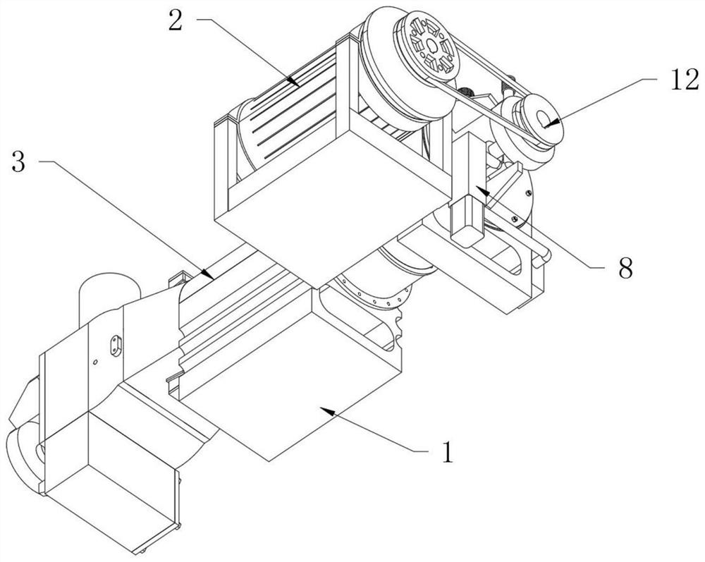

Image

  • Burner facility for biomass boiler combustion system
  • Burner facility for biomass boiler combustion system
  • Burner facility for biomass boiler combustion system

Examples


Embodiment Construction

[0031] Embodiments of the present invention will be further described in detail below in conjunction with the accompanying drawings and examples. The following examples are used to illustrate the present invention, but should not be used to limit the scope of the present invention.

[0032] In the description of the present invention, unless otherwise stated, the meaning of "plurality" is two or more; the terms "upper", "lower", "left", "right", "inner", "outer" , "front end", "rear end", "head", "tail", etc. indicate the orientation or positional relationship based on the orientation or positional relationship shown in the drawings, and are only for the convenience of describing the present invention and simplifying the description, rather than Nothing indicating or implying that a referenced device or element must have a particular orientation, be constructed, and operate in a particular orientation should therefore not be construed as limiting the invention. In addition, t...


PUM


Abstract

The invention provides a burner facility of a biomass boiler combustion system, which includes a base, a dust-blocking plate and an ash leakage tray; a longitudinal cylindrical burner body is fixedly installed on the top of the base; the burner body The left end is fixedly provided with a feeding cabin, while the right end of the burner body is fixedly provided with a heat collecting cabin; the upper end of the feeding cabin is vertically provided with an air inlet pipe. The present invention provides a burner facility for a biomass boiler combustion system. Its feed cabin and gas distribution pipe are arranged, and an interlayer is provided through the part of the feed cabin close to the shell, and the gas distribution pipe is connected in a fire-stopping ring in two layers inside and outside. The other end of the air distribution pipe is inserted into the interlayer of the feed cabin, so that the air entering the intake pipe can be evenly distributed in the interlayer of the feed cabin in advance, and then diffused evenly to the fire arresting plate by the air distribution pipe to avoid Air flow is disturbed, resulting in increased fly ash production.

Description

technical field [0001] The invention relates to the technical field of biomass treatment, and more specifically relates to a burner facility of a biomass boiler combustion system. Background technique [0002] The existing energy is generally dominated by coal, oil, natural gas, etc. With the massive consumption of energy, energy will become more and more scarce. In the case of energy shortage, people urgently need new energy to replace coal, oil, natural gas, etc. New energy includes wind energy, solar energy, biomass, etc. Biomass energy mainly includes crop straw, etc., and crop straw has the advantages of large quantity and low cost and has been widely used. The use of biomass energy requires putting crop stalks into the combustion furnace for burning to provide energy. [0003] Through the technical analysis of the burner facilities of the biomass boiler combustion system by technicians, it is found that when the existing biomass pellet burner burns, due to the small ...

Claims


Application Information

Patent Timeline
Patent Type & Authority Patents(China)
IPC IPC(8): F23C3/00F23C9/06F23D1/02F23J3/06
CPCF23C3/008F23C9/06F23D1/02F23J3/06
Inventor 沈涛洋
Owner 陕西分布式能源股份有限公司
Learn More