Rotary type erosion corrosion test device

A technology for scouring corrosion and testing equipment, which is applied to measuring equipment, testing wear resistance, instruments, etc., can solve the problems of high testing cost, large solution, splashing, etc., and achieve high temperature testing, easy container cleaning, and convenient disassembly Effect

Pending Publication Date: 2020-01-03
无锡纽思铁科能源科技有限公司
View PDF0 Cites 7 Cited by
  • Summary
  • Abstract
  • Description
  • Claims
  • Application Information

AI Technical Summary

Problems solved by technology

The existing rotary type mostly uses the impeller to rotate, and the sample is placed on the inner wall of the solution tank. This installation method facilitates the electrical connection of the sample, but this method causes the test solution to wash the sample at a low speed, which cannot be effectively simulated. The erosion and corrosion of the pump impeller, the accuracy of the test results is not good
[0005] At present, the effective scouring of the sample is mostly achieved by increasing the diameter of the container or increasing the rotational speed of the test solution. The purpose of increasing the diameter is to increase the rotational speed of the outermost side of the test solution, because the sample is located at this position, so as to improve the speed of the sample. However, the speed of the test solution should not be too high. If the speed of the test solution is too high, a large vortex will be formed in the center of the test solution, and the top surface of the test solution will form a cone. Produces large solution splashes
This method requires more test solutions, higher power motors, higher test costs, and limited improvement to the actual working conditions of simulated pumps and blades

Method used


Image

  • Rotary type erosion corrosion test device
  • Rotary type erosion corrosion test device
  • Rotary type erosion corrosion test device

Examples


Embodiment 1

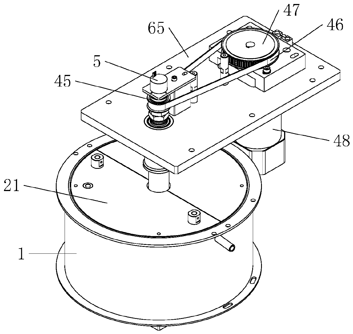
[0047] Such as Figure 1 to Figure 11 As shown, a rotary erosion corrosion test device includes a container 1, a motor 48 and an electrode 24, and the electrode 24 is located in the container 1; it also includes a rotating disk, which is located in the container 1; On the rotating disk, there are multiple sample fixing devices for fixing the sample 30; the transmission shaft, one end of the transmission shaft is connected with the rotating disk, and the other end is connected with the motor 48; and the conductive device, the conductive device is installed on the transmission shaft and On the rotating disk, and located inside the transmission shaft and the transmission disk, the conductive device is used for communication between the sample 30 and the electrochemical testing device.

[0048] Through the high-speed rotation of the sample 30 in the test solution to simulate the situation of pumps, blades and other high-speed propulsion medium flow channels, which is basically clo...

Embodiment 2

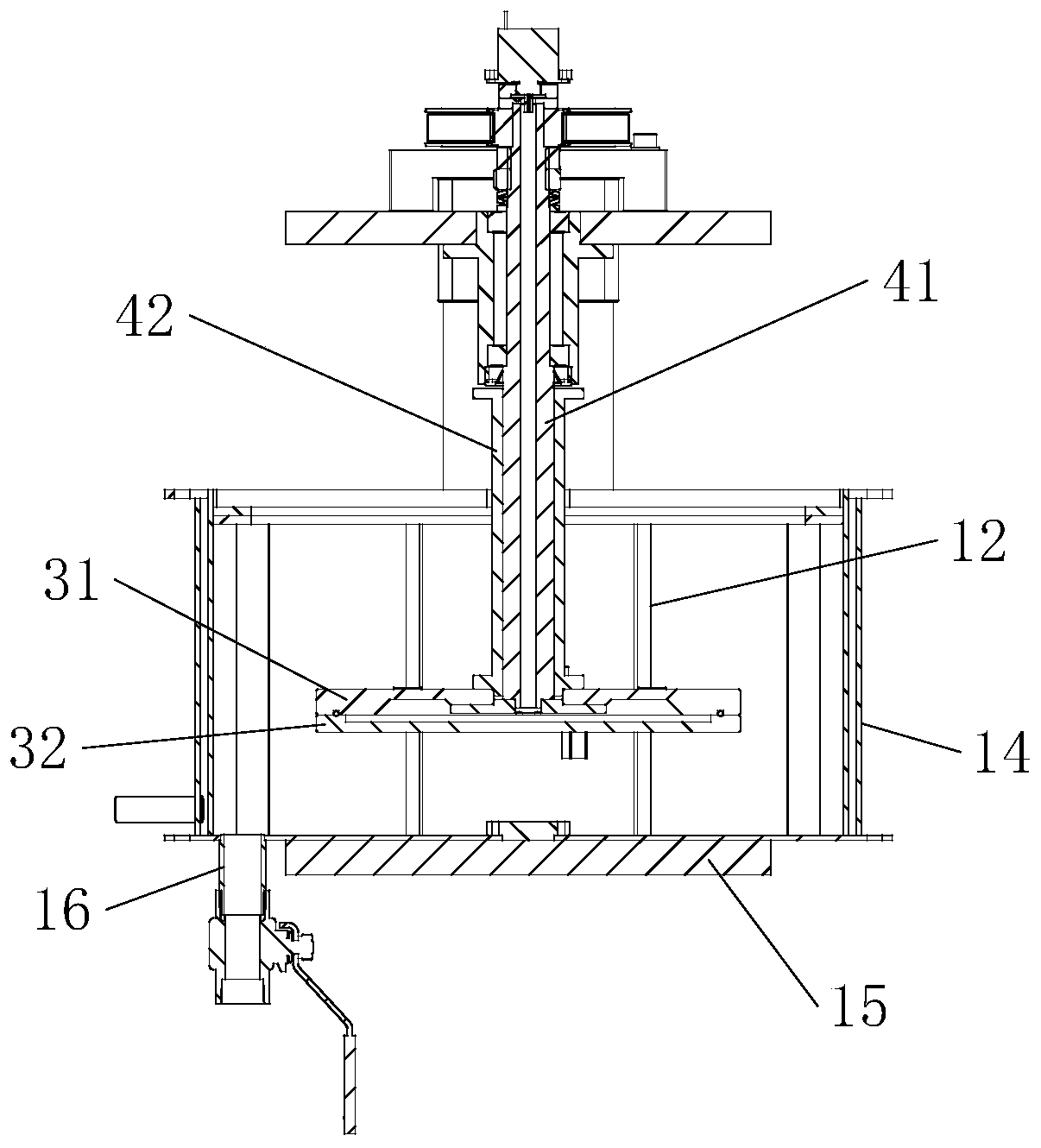
[0076] On the basis of the first embodiment above, the bottom of the lower turntable 32 is provided with a stirring plate 39 , and there are multiple stirring plates 39 in an annular array, and the stirring plate 39 is used to stir the gravel at the bottom of the container 1 .

[0077] The stirring plate 39 stirs the gravel at the bottom of the container 1 to prevent the gravel from gathering in the middle of the bottom of the container 1, because the test solution at the center of the container 1 rotates slowly when the test solution in the container 1 rotates, causing the gravel to accumulate and cause the scour area The sand content of the test solution is low, and the stirring plate 39 can stir the gravel at the bottom of the container 1 to improve the sand content in the scoured area.

Embodiment 3

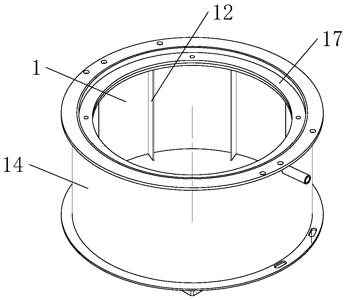
[0079] On the basis of the above-mentioned embodiment one or embodiment two, as image 3 and Figure 4 As shown, the container 1 is cylindrical, with an opening at the top and a closed bottom. The interior of the container 1 is provided with spoilers 12 , and a plurality of spoilers 12 are arranged in a circular array along the axis of the container 1 .

[0080] The spoiler 12 makes the test solution form a vortex, and the direction of rotation of the vortex is opposite to the direction of rotation of the rotating disk. The direction of rotation of the test solution is consistent with that of the rotating disk, but the rotational speed of the test solution is far less than that of the rotating disk, and the disturbing The direction of rotation of the vortex formed by the flow plate 12 is opposite to the direction of rotation of the test solution, so it forms a larger speed difference with the sample 30, and the sample 30 on the rotating disk passes through the vortex, thus great...


PUM


Abstract

The invention relates to a corrosion test device, in particular to a rotary type erosion corrosion test device. The rotary type erosion corrosion test device comprises a container, a motor and an electrode located in the container and also comprises a rotary disc located in the container, multiple sample fixing devices which are mounted on the rotary disc and used for fixing samples, a transmission shaft and a conductive device, wherein one end of the transmission shaft is connected with the rotary disc, the other end of the transmission shaft is connected with the motor, and the conductive device is mounted on the transmission shaft and the rotary disc and used for communication between the samples and an electrochemical test device. The rotary type erosion corrosion test device providedby the invention can accurately and effectively simulate erosion corrosion conditions of rotating parts such as a pump and a blade in a solid-liquid dual-phase fluid and can realize a real-time electrochemical test at a high rotating speed, the samples can be conveniently dismounted, the container is easy to clean, and a high-temperature test can be realized.

Description

technical field [0001] The invention relates to a corrosion test device, in particular to a rotary erosion corrosion test device. Background technique [0002] Corrosion of metals under flowing medium conditions widely exists in various industries such as petroleum, chemical industry, electric power, nuclear power, and ships. Therefore, the research on flow erosion corrosion has a very large application background. Unlike the corrosion of metals in static solutions, fluid flow increases the mass and oxygen transfer processes in the corrosion process, thereby accelerating the corrosion rate. If the fluid contains solid-phase particles to form a liquid-solid two-phase flow, the solid-phase particles will also cause mechanical damage to the surface of the material by impact and wear. Under the interaction of mechanical damage and chemical corrosion damage, the damage degree of the material is often greater than that of the material alone. The damage is greater, which directly...

Claims


Application Information

Patent Timeline
Patent Type & Authority Applications(China)
IPC IPC(8): G01N3/56
CPCG01N3/565G01N3/567
Inventor 陈建栋邱晓波袁丽丽徐华陈磊
Owner 无锡纽思铁科能源科技有限公司
Why Eureka
Try Eureka