Primary iron core staggered driving structure, a linear motor and numerical control equipment

A primary iron core and drive structure technology, applied in the direction of electrical components, electromechanical devices, electric components, etc., can solve the problem of increased normal suction force, achieve the effect of reducing the size of the motor, increasing the thrust density, and offsetting the normal magnetic attraction force

Active Publication Date: 2020-01-03
GREE ELECTRIC APPLIANCES INC
View PDF6 Cites 6 Cited by
  • Summary
  • Abstract
  • Description
  • Claims
  • Application Information

AI Technical Summary

Problems solved by technology

There is also a way to increase the thrust density by increasing the number of movers in the horizontal and vertical directions, but the normal suction in this way is doubled

Method used


Image

  • Primary iron core staggered driving structure, a linear motor and numerical control equipment
  • Primary iron core staggered driving structure, a linear motor and numerical control equipment
  • Primary iron core staggered driving structure, a linear motor and numerical control equipment

Examples


Embodiment 1

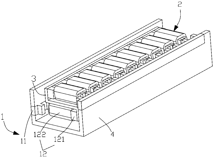
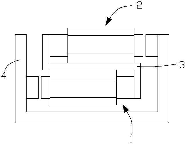
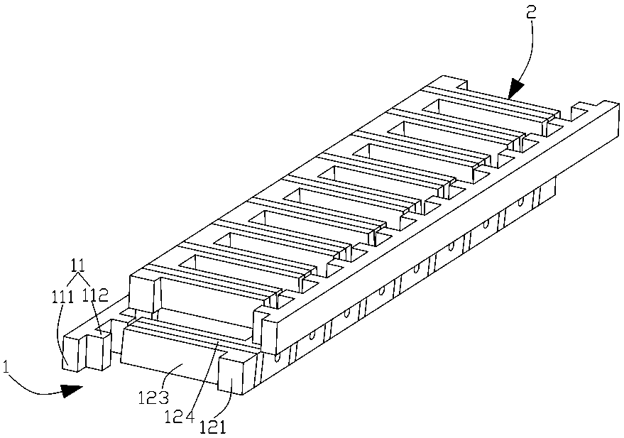
[0026] refer to Figure 1 to Figure 6 , A primary iron core staggered drive structure provided by the present invention includes a first drive assembly 1 and a second drive assembly 2 stacked in sequence, and a connecting piece 3 for connecting the first drive assembly and the second drive assembly. The adjacent first drive assembly and the second drive assembly form a linear drive mechanism, and the linear drive mechanism has at least one (if there are two linear drive mechanisms, then 2 first drive assemblies and 2 second drive assemblies are staggered and superimposed, so that and so on); the first drive assembly and the second drive assembly have the same structure, both including a stator 11, a mover 12 arranged on one side of the stator for driving the movable object to move linearly along the stator, the first drive assembly Set opposite to the second drive assembly, define the movement direction of the mover as the X-axis direction, then the direction perpendicular to ...

Embodiment 2

[0036] In this embodiment, two linear drive mechanisms are superimposed, that is, there are two first drive assemblies and two second drive assemblies, and they are stacked alternately in sequence. Apart from this, other parts of the structure of this embodiment are the same as those of Embodiment 1, and will not be repeated here. During specific implementation, n linear drive mechanisms can be stacked, and the number of the first drive assembly and the second drive assembly is also corresponding to n, so that the number of iron cores (primary iron cores and secondary iron cores) can be doubled. For example, when there are 4 linear drive mechanisms stacked, there are 4 first drive assemblies and 4 second drive assemblies respectively. The components of the filler can be set according to specific implementations.

[0037] The present invention also provides a linear motor (not shown in the drawings), which includes the aforementioned primary iron core interleaved drive structu...


PUM


Abstract

The invention relates to a primary iron core staggered driving structure, a linear motor and numerical control equipment. The primary iron core staggered driving structure comprises first driving assemblies and second driving assemblies superposed in turn, and connecting pieces used for connecting the first driving assemblies and the second driving assemblies. The first driving assemblies and thesecond driving assemblies form at least one linear driving mechanism. According to the invention, the first driving assemblies and the second driving assemblies are sequentially staggered and superposed, which can multiply the number of iron cores. The two driving assemblies are arranged in opposite directions in the direction perpendicular to the moving direction of the rotor, so that the primaryiron cores are staggered in the vertical direction, the size of the motor can be reduced, the thrust density can be improved, the cogging force of the linear motor is reduced, and the operation stability is improved. On the other hand, the first driving assemblies and the second driving assemblies which are superposed in a staggered mode can counteract normal magnetic attraction force.

Description

technical field [0001] The invention relates to the technical field of linear drive feed for intelligent equipment machine tools, in particular to a primary iron core interleaved drive structure, a linear motor and numerical control equipment. Background technique [0002] Linear motor, also known as linear motor, linear motor, linear motor, push rod motor, is a transmission device that directly converts electrical energy into linear motion mechanical energy without any intermediate conversion mechanism, and can be used to realize linear transmission, positioning, guidance, etc. Compared with rotating motors, it has the characteristics of high thrust density, fast response speed, high system rigidity and simple structure. It is more and more widely used in high-end CNC machine tools, high-speed rail transportation and IT industry equipment and other fields. In order to increase the thrust density of the linear motor, it is generally possible to increase the stack height of t...

Claims


Application Information

Patent Timeline
Patent Type & Authority Applications(China)
IPC IPC(8): H02K41/02H02K41/03
CPCH02K41/02H02K41/031H02K2213/03
Inventor 郑立章谢芳焦雷刘伟健郜曦张智超赖奕霖张海斌刘建国
Owner GREE ELECTRIC APPLIANCES INC
Why Eureka
Try Eureka