Housing components and electronics

A shell component and shell technology, applied in the direction of electrical equipment shell/cabinet/drawer, casing/cabinet/drawer parts, electrical components, etc., can solve the problem of affecting the radiation performance of millimeter wave antennas and cannot meet practical applications , Antenna efficiency decline and other issues, to achieve the effect of avoiding appearance defects, high practical application value, and small signal loss

Active Publication Date: 2021-06-08
GUANGDONG OPPO MOBILE TELECOMM CORP LTD
View PDF25 Cites 0 Cited by
  • Summary
  • Abstract
  • Description
  • Claims
  • Application Information

AI Technical Summary

Problems solved by technology

[0003] However, the existing millimeter-wave antenna modules are generally only suitable for free space environments. If they are placed directly in the complete electronic device, due to the coverage effect of the back cover of the device, the radiation performance of the millimeter-wave antenna will be affected, resulting in a decrease in antenna efficiency, etc. problem, unable to meet the practical application

Method used


Image

  • Housing components and electronics
  • Housing components and electronics
  • Housing components and electronics

Examples


Embodiment 1

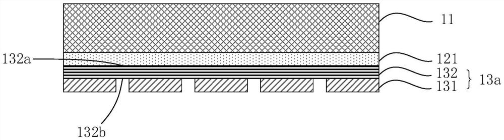
[0058] The housing assembly structure of the present embodiment is like figure 1 Indicated. Among them, the material of the housing 11 is glass, the bonding layer 121 is a adhesive, and the substrate 132 is a PET film. The conductive silver paste is used, and the frequency selection surface structure consisting of a plurality of circular cells is printed by the screen printing process. The arrangement of the plurality of circular units is arranged. Figure 28 The rectangular array shown, each of the circular cells is 0.5 mm, and the distance between the center of the adjacent two circular units is 1 mM to obtain the transmission layer 13a. The transparent wave layer 13a is attached to the housing 11 by the adhesive layer 121 to obtain a housing assembly, the housing assembly having a total thickness of 0.7 mm.

[0059] Test the reflection coefficient and transmitting coefficient of 20 to 34 GHz, the test result is: the scattering coefficient of 22.4 GHz ~ 29.5 GHz after the housing...

Embodiment 2

[0061] The housing assembly structure of the present embodiment is like Figure 9 Indicated. Wherein, the material of the housing 11 is glass, and the decorative layer 122 is a CMF diaphragm. The conductive silver paste is used, and the screen printing process is printed by the screen printing process by the remote from the housing 11 of the decorative layer 122, the frequency selection surface structure consisting of a plurality of square units, and the arrangement of the plurality of square units is a rectangular array, each square The radius of the unit is 1 mm, the distance between the two square units is 2 mm, and the transmission layer 13f is obtained; and the conductive silver paste is used, and the wire screen printing process is printed from the side of the housing 11 of the decorative layer 122. The frequency selection surface structure consisting of multiple grid units, and the arrangement of multiple grid units is like Figure 11 The rectangular array shown, the line wid...


PUM

PropertyMeasurementUnit
widthaaaaaaaaaa
widthaaaaaaaaaa
diameteraaaaaaaaaa

Abstract

The present invention relates to a housing assembly and an electronic device, the housing assembly comprises a laminated housing, a functional layer and a wave-transmitting layer, the functional layer includes at least one of an adhesive layer and a decorative layer, the The wave-transmitting layer is connected with the functional layer, and the wave-transmitting layer has a frequency-selective surface structure, and the frequency-selective surface structure is used to make the shell transmit millimeter waves with a frequency of 24.25GHz˜52.6GHz. The shell assembly shown has a special frequency-selective surface structure, which can produce frequency selectivity for electromagnetic waves, so that the shell assembly exhibits high-efficiency wave transmission characteristics for the millimeter-wave frequency band, thereby significantly reducing the impact on the radiation performance of the millimeter-wave antenna module. influences.

Description

Technical field [0001] The present invention relates to the field of wireless communication, and more particularly to a housing assembly and an electronic device. Background technique [0002] According to the 3GPP TS 38.101 protocol, 5G NR mainly uses two frequency bands: FR1 band and FR2 band. The frequency range of the FR1 band is 450MHz to 6GHz, also known as the SUB-6GHz band; the frequency range of the FR2 band is 24.25 GHz to 52.6GHz, which is often referred to as millimeter wave (MM Wave). The millimeter wave has high carrier frequencies, large bandwidth and other characteristics, providing high-speed transmission. At present, Qualcomm has released two millimeter wave antenna modules QTM052 and QTM525 modules, where the QTM052 module covers 3GPP N261 and N260 Band, and the QTM525 module covers 3GPP N258 and N261 Band. [0003] However, the existing millimeter wave antenna module generally applies only to free space environments, and if it is placed directly in the electro...

Claims


Application Information

Patent Timeline
Patent Type & Authority Patents(China)
IPC IPC(8): H05K5/02H01Q1/22
CPCH01Q15/0006H05K5/0217B32B33/00B32B27/36B32B7/12
Inventor 杨自美
Owner GUANGDONG OPPO MOBILE TELECOMM CORP LTD
Why Eureka
Try Eureka