Covered stent and manufacturing method thereof

A covered stent and the technology of its manufacturing method are applied in the direction of stents, human body tubular structure devices, blood vessels, etc., and can solve problems such as uneven lumen of covered stents

Pending Publication Date: 2020-01-07
SHANGHAI VASOLUTIONS MEDTECH CO LTD
View PDF0 Cites 0 Cited by
  • Summary
  • Abstract
  • Description
  • Claims
  • Application Information

AI Technical Summary

Problems solved by technology

[0006] The purpose of the present invention is to provide a stent-graft and a method for making the stent-graft to solve the problem that the lumen of the stent-graft is not smooth

Method used


Image

  • Covered stent and manufacturing method thereof
  • Covered stent and manufacturing method thereof
  • Covered stent and manufacturing method thereof

Examples


Embodiment 1

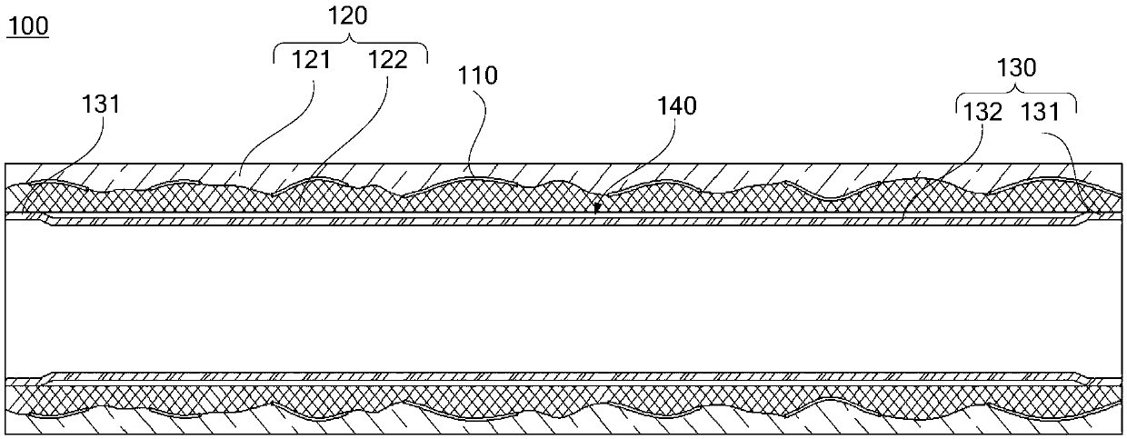
[0031] This embodiment provides a stent graft. figure 1 is a cross-sectional view of the stent graft in Embodiment 1 of the present invention, refer to figure 1 , the stent graft 100 includes a skeleton 110 , a skeleton covering 120 and an inner covering 130 , and the skeleton covering 120 includes an outer covering 121 and a middle covering 122 . The outer coating 121 is arranged on the entire outer peripheral surface of the skeleton 110, the middle coating 122 is arranged on the entire inner peripheral surface of the skeleton 110, and the outer coating 121, the middle layer The covering film 122 and the frame 110 are bonded together in pairs. The inner coating 130 is disposed in the lumen of the stent graft 100 , specifically, the inner coating 130 is disposed on the entire inner wall of the middle coating 122 . The inner coating 130 includes N sections of adhesive section 131 and M sections of separation section 132. In this embodiment, N=2, M=N-1, and both ends of the in...

Embodiment 2

[0045] This embodiment provides a stent graft. The difference between the stent-graft in this embodiment and the stent-graft in Embodiment 1 is that the number of bonding sections in this embodiment is N≥3. The plurality of separation sections and the middle layer coating form a plurality of hollow layers, and the plurality of hollow layers are arranged alternately along the axial direction of the frame.

[0046] Figure 5 It is a cross-sectional view of the stent graft in Example 2 of the present invention, refer to Figure 5 , the plurality of bonding segments 131 of the inner layer coating 130 are respectively bonded together with the middle layer coating 122, and the plurality of separation segments 132 and the middle layer coating 122 form a plurality of hollow layers 140, And a plurality of the hollow layers 140 are arranged alternately along the axial direction of the framework 110 .

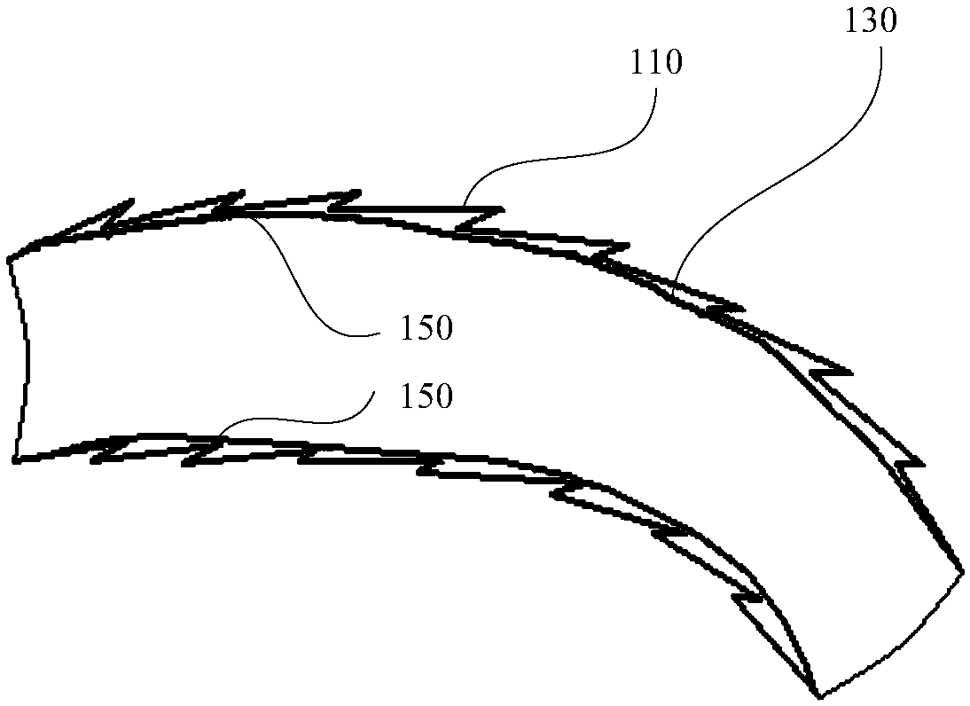
[0047] Since the inner layer coating 130 is relatively soft and cannot be bent and...

Embodiment 3

[0052] This embodiment provides a stent graft. Figure 6 It is a cross-sectional view of the stent graft in Example 3 of the present invention, refer to Figure 6 The difference between the stent-graft 100 in this embodiment and the stent-graft 100 in Embodiment 1 is that the inner layer of the stent-graft 130 in this embodiment is arranged at the proximal end of the skeleton 110 away from the skeleton 110 and In the area away from the distal end of the skeleton 110, that is, the length of the inner layer membrane 130 in the axial direction is smaller than the length of the stent graft 100, and both ends of the inner layer membrane 130 are not connected to the The two ends of the stent graft 100 overlap, and the adhesive sections 131 at both ends of the inner layer coating 130 are respectively bonded to the middle layer coating 122, and the separation section 132 of the inner layer coating 130 is connected to the middle layer The covering films 122 together form a hollow laye...


PUM

PropertyMeasurementUnit
Lengthaaaaaaaaaa
Lengthaaaaaaaaaa
Lengthaaaaaaaaaa

Abstract

The invention provides a covered stent and a manufacturing method thereof, and belongs to the field of implantable medical apparatus and instruments. The covered stent comprises a skeleton, a skeletontectorial membrane and an inner-layer tectorial membrane; the skeleton tectorial membrane is arranged on the skeleton, and the skeleton tectorial membrane and the skeleton are mutually bonded together; the inner-layer tectorial membrane is arranged in an inner cavity of a covered stent defined by the skeleton tectorial membrane and the skeleton, and comprises N bonded segments and M separated segments, wherein N is larger than or equal to 2, and M is equal to N minus 1; the bonded segments and the separated segments are alternately arranged at intervals in the axial direction of the skeletontectorial membrane and connected into a whole; and the bonded segments are bonded with the skeleton tectorial membrane and the skeleton, and a hollow layer is formed between the separated segments andthe skeleton tectorial membrane. By additionally arranging the layer of inner-layer tectorial membrane in the inner cavity in the ordinary covered stent, the inner wall of the covered stent can be smooth.

Description

technical field [0001] The invention relates to the field of implanted medical devices, in particular to a stent-graft and a method for making the stent-graft. Background technique [0002] In the field of implanted medical devices, ePTFE-covered stents have been widely recognized in recent years, and their advantages include excellent biocompatibility and ultra-slip properties. The indications for this type of stent graft include peripheral vascular embolism, aortic and branch dissection, aortic and branch true aneurysm, aortic and branch pseudoaneurysm, aortic and branch penetrating ulcer, etc. The implantation operation using the covered stent greatly reduces the operation mortality rate and postoperative complications, and can reduce the operation trauma at the same time, and the patient recovers quickly. The mechanism of this implantation operation is to send the covered stent into the lesion through a special delivery system and then open it, so as to open the blood v...

Claims


Application Information

Patent Timeline
IPC IPC(8): A61F2/07
CPCA61F2/07
Inventor 夏顺叶猛刘梦钦郭芳袁振宇朱清
Owner SHANGHAI VASOLUTIONS MEDTECH CO LTD
Why Eureka
Try Eureka