Stainless steel strip automatic winding machine

A technology for winding machinery and stainless steel strips, applied in the field of automatic winding machinery for stainless steel strips, can solve the problems of movement of stainless steel strips, insufficient utilization of resources, and different effects of bundling and forming, so as to reduce the phenomenon of offset movement. probability, increase utilization and work efficiency, reduce the effect of the probability of drift phenomenon

Active Publication Date: 2020-01-07
日照市中腾机械有限责任公司
View PDF7 Cites 3 Cited by
  • Summary
  • Abstract
  • Description
  • Claims
  • Application Information

AI Technical Summary

Problems solved by technology

[0003] 1. The diameter of the winding core usually used for winding is a fixed size, and only one type of stainless steel coil can be wound and formed. Faced with different requirements, different winding cores need to be used, which will easily cause redundant equipment and resources. At the same time, the stainless steel strip is compacted without a compression limit device during winding, which is prone to relaxation, the tightness of the winding is low, and the stainless steel strip is also prone to movement, which affects the winding process. have an impact;
[0004] 2. Usually, after the coiling of the stainless steel strip is completed, it cannot be bundled in time, and the stainless steel strip coil is prone to explode outwards, forming a loose state, so that secondary winding is required, which increases the processing cost and Work intensity, the work efficiency of manual binding of stainless steel strip coils is low, and the strength of each worker is different, the effect of binding and forming is also different, and the quality of the formed products cannot be effectively guaranteed

Method used


Image

  • Stainless steel strip automatic winding machine
  • Stainless steel strip automatic winding machine
  • Stainless steel strip automatic winding machine

Examples


Embodiment Construction

[0031] The embodiments of the present invention will be described in detail below with reference to the accompanying drawings, but the present invention can be implemented in many different ways as defined and covered by the claims.

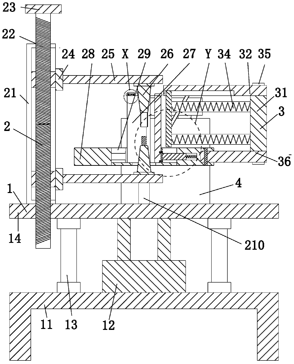
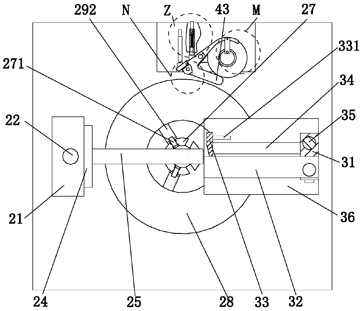
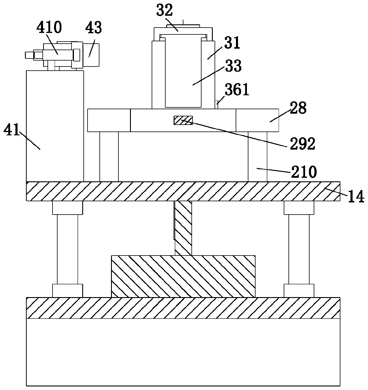
[0032] Such as Figure 1 to Figure 8 As shown, a stainless steel strip automatic winding machine includes a transmission device 1, a core expansion device 2, a limit device 3 and a cloth patching device 4. The upper end of the transmission device 1 is equipped with a core expansion device 2, and the core expansion device The limit device 3 is installed on the right end of the device 2 , and the cloth sticking device 4 is installed on the rear end of the upper end surface of the transmission device 1 , and the cloth sticking device 4 is located at the rear side of the core expanding device 2 .

[0033] The core expansion device 2 includes a slide rail plate 21, a screw 22, a runner 23, a slider 24, a mounting plate 25, a core expansion shaft 26, a...


PUM


Abstract

The invention relates to a stainless steel strip automatic winding machine. The machine comprises a transmission device, a core expanding device, a limiting device and a cloth pasting device; the coreexpanding device is mounted at the upper end of the transmission device; the limiting device is mounted at the right end of the core expanding device; the cloth pasting device is mounted at the backend of the upper end surface of the transmission device; and the cloth pasting device is positioned on the back side of the core expanding device. The stainless steel strip automatic winding machine adopts an adjustable multi-limiting design idea to wind stainless steel strips to meet different sizes and types of stainless steel strip coils, and adopts the limiting device to limit the stainless steel strips to reduce the deviation phenomenon occurrence probability and to greatly reduce the looseness phenomenon occurrence possibility.

Description

technical field [0001] The invention relates to the field of cutting machines, in particular to an automatic winding machine for stainless steel strips. Background technique [0002] Stainless steel refers to steel resistant to weak acid corrosion media such as air, steam, water, and chemical corrosion media such as acid, alkali, and salt. It is also called stainless steel. In practical applications, steel resistant to weak acid corrosion media is often called stainless steel. , and the steel resistant to chemical corrosion medium corrosion is called acid-resistant steel, stainless steel can be divided into austenitic stainless steel, ferritic stainless steel and other types, which have weldability, corrosion resistance, polishability, heat resistance and other advantages, and are used in many fields such as construction, machinery, automobiles, chemicals, etc. According to the use or requirements of the products, various types of finished products such as stainless steel sh...

Claims


Application Information

Patent Timeline
Patent Type & Authority Applications(China)
IPC IPC(8): B65H75/24B65H75/14B65H75/28B65H19/30
CPCB65H19/30B65H75/14B65H75/241B65H75/28
Inventor 郭新红马妮娜
Owner 日照市中腾机械有限责任公司
Why Eureka
Try Eureka