Optical signal intelligent lock based on embedded system

An embedded system, optical signal technology, applied in the field of smart locks, can solve the problems of poor anti-theft performance, difficult to remedy, easy to copy, etc., to achieve the effect of improving security, easy production, and increasing complexity

Inactive Publication Date: 2020-01-07
SHANGHAI DIANJI UNIV
View PDF13 Cites 0 Cited by
  • Summary
  • Abstract
  • Description
  • Claims
  • Application Information

AI Technical Summary

Problems solved by technology

[0005] At present, most of the civil locks are based on the traditional key design of mechanical structure, which has the disadvantages of easy duplication and poor anti-theft performance; a small nu...

Method used


Image

  • Optical signal intelligent lock based on embedded system
  • Optical signal intelligent lock based on embedded system
  • Optical signal intelligent lock based on embedded system

Examples


Embodiment Construction

[0031] In order to make the technical means, creative features, goals and effects achieved by the present invention easy to understand, the present invention will be further described below in conjunction with specific embodiments.

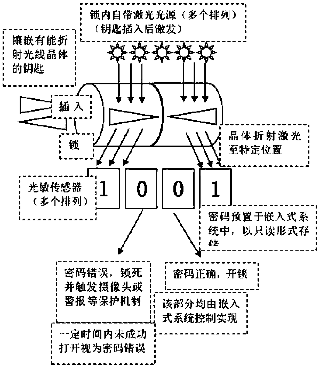
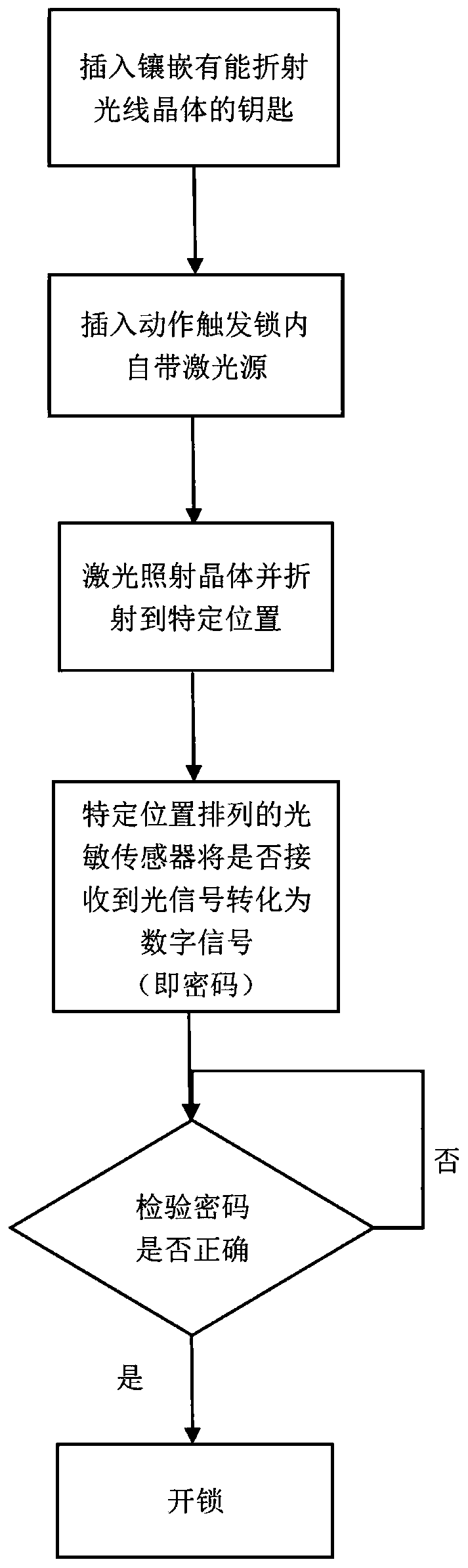
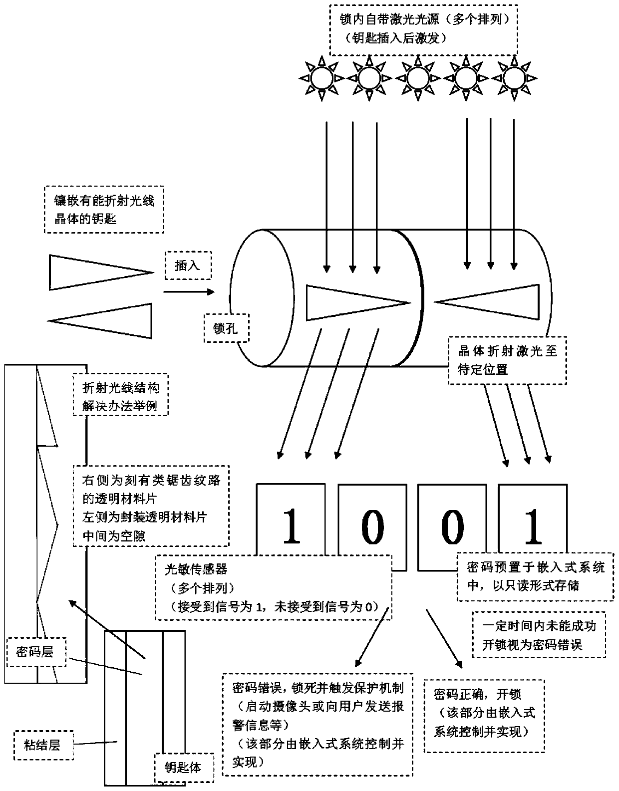
[0032] see Figure 1 to Figure 3 According to the present invention, an optical signal smart lock based on an embedded system includes a key. The main body of the key is a sheet structure, and a number of light-transmitting crystals are embedded on the sheet structure. When light passes through the crystal, it will The information recorded on the key is read out in the form of optical signals;

[0033] A lock cylinder, a laser module and a photoelectric module are arranged in the lock cylinder;

[0034] A laser module, the laser module includes several laser tubes, and the laser tube is arranged on one side of the key insertion area in the lock cylinder; a photoelectric module, the photoelectric module includes several photoelectric sensors, and ...


PUM


Abstract

The invention discloses an optical signal intelligent lock based on an embedded system. By taking a transmitting crystal capable of refracting rays as a key, a lock cylinder is formed by a laser module and a photosensory photoelectric module. If being electrified, when parallel beams emitted by the laser module penetrate the key, a code on the key is read out in a form of an optical signal and isirradiated to photosensory photoelectric module. The photoelectric module converts the code into an electric signal which is transferred to a control chip. The control chip obtaining the electric signal code judges whether the code is correct or not, if so, unlocking or other unlocking triggering action is performed, and if not, locking, other locking action or no action is performed.

Description

technical field [0001] The present invention relates to the field of intelligent locks, in particular to an optical signal intelligent lock based on an embedded system. Background technique [0002] At present, most civilian locks are based on the traditional key design of mechanical structure, and a small number of locks are magnetic card locks based on electromagnetic signals. [0003] Magnetic card door lock is composed of access controller, card reader, communication converter, access control software and electronic door lock. Its card reading method is a non-contact card reading method. As long as the cardholder shakes the card near the card reader (5-15 cm) quickly, the card reader can sense the presence of the card and read the information (card number) in the card. sent to the host. The host computer checks the legitimacy of the card, and then decides whether to open the door. [0004] The working principle of the electronic door lock is: in the power-on state, af...

Claims


Application Information

Patent Timeline
IPC IPC(8): E05B49/00E05B47/00E05B19/26E05B19/04E05B19/08
CPCE05B19/0011E05B19/0017E05B19/26E05B47/0012E05B49/006E05B2047/0084
Inventor 朱颖杰丁晓岚潘嘉杰张华
Owner SHANGHAI DIANJI UNIV
Why Eureka
Try Eureka