Single-phase three-level power factor correction rectifier based on symmetrical four ports

A power factor correction, four-port technology, applied in the field of single-phase three-level power factor correction rectifiers, can solve the problems of voltage and current power factor, low current power factor, etc., and achieve the effect of improving short-term power supply demand

CN110661413AActive Publication Date: 2020-01-07CHINA THREE GORGES UNIV
7 Cites 9 Cited by

Patent Information

Authority / Receiving Office
CN · China
Current Assignee / Owner
Publication Date
2020-01-07

Smart Images

  • Figure 1
    Figure 1
  • Figure 2
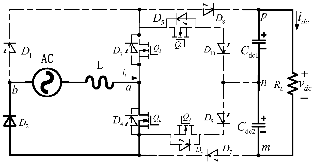
    Figure 2
  • Figure 3
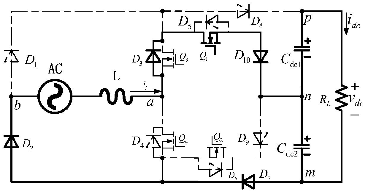
    Figure 3
Patent Text Reader

Abstract

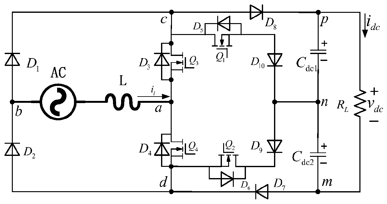
The invention relates to a single-phase three-level power factor correction rectifier based on asymmetric four ports. The rectifier comprises an alternating-current power source AC, an inductor L, switching tubes (Q1, Q2, Q3 and Q4), diodes (D1, D2, D7, D8, D9 and D10), and capacitors (Cdc1 and Cdc2); one side of the alternating-current power source AC is connected with the anode of the diode D1 and the cathode of the diode D2, and the connection node of the alternating-current power source AC, the diode D1 and the diode D2 form an end point b; the other side of the alternating-current power source AC is connected with one end of the inductor L; the other end of the inductor L is connected with the source electrode of the switching tube Q3 and the drain electrode of the switching tube Q4,and the connection node of the inductor L, the switching tube Q3 and the switching tube Q4 form an end point a; the drain electrode of the switching tube Q3 is connected with the cathode of the diodeD1 and the anode of the diode D8, and the connection node of the switching tube Q3 and the diode D8 forms an end point c; the source electrode of the switching tube Q4 is connected with the anode of the diode D2 and the cathode of the diode D7, and the connection node of the switching tube Q4, the diode D2 and the diode D7 forms an end point d; the cathode of the diode D8 is connected with one endof the capacitor Cdc1, and the connection node of the diode D8 and the capacitor Cdc1 forms an end point p; the other end of the capacitor Cdc1 is connected with one end of the capacitor Cdc2, and the connection node of the capacitor Cdc1 and the capacitor Cdc2 forms an end point n; and the other end of the capacitor Cdc2 is connected with the anode of the diode D7, and the connection node of thecapacitor Cdc2 and the diode D7 forms an end point m. The topological structure of the rectifier can adopt a multi-carrier modulation mode to control different circuit modes.
Need to check novelty before this filing date? Find Prior Art

Description

technical field

[0001] The invention relates to the technical field of single-phase electric energy conversion, in particular to a single-phase three-level power factor correction rectifier based on symmetrical four ports. Background technique

[0002] In today's industrial applications, there is a large demand for DC power. In the conversion of electric energy, the conversion of AC voltage into DC is usually used for DC-DC conversion. In the process of rectification, usually because the waveform of the current cannot The completely more voltage-dependent waveform leads to a lower power factor in the rectification process. The power factor rectifier has been proposed for many years to overcome the problem of voltage and current power factor on the AC side.

[0003] Rectification is ubiquitous in industrial applications, and it will be applied to the rectification process under different voltage levels. In the current high-voltage direct current transmission process, it is ne...

Examples

Embodiment Construction

[0058] Such as figure 1 As shown, based on asymmetric four-port single-phase three-level power factor correction rectifier, including:

[0059] Including AC power supply, inductor L, switch tube Q 1 , Q 2 , Q 3 , Q 4 , Diode D 1 、D 2 、D 7 、D 8 、D 9 、D 10 , capacitance C dc1 、C dc2 ;

[0060] The AC side of the AC power supply is connected to the diode D 1 anode, diode D 2 a cathode connected to the nodes forming terminal b;

[0061] The other side of the AC power supply AC is connected to one end of the inductor L, and the other end of the inductor L is connected to the switch tube Q 3 Source, switch tube Q 4 Drains connected to nodes forming terminal a;

[0062] Switch tube Q 3 The drains are connected to the diode D 1 cathode, diode D 8 an anode, the junction of which constitutes terminal c;

[0063] Switch tube Q 4 The source is connected to the diode D respectively 2 anode, diode D 7 a cathode connected to the nodes forming terminal d;

[0064] Dio...