Crushing device of garbage classification system
A crushing device and garbage sorting technology, which is applied in the direction of solid separation, filter screen, grille, etc., can solve the problems of small and single output torque of the motor, and can not be well qualified for garbage crushing work, etc.
- Summary
- Abstract
- Description
- Claims
- Application Information
AI Technical Summary
Problems solved by technology
Method used
Image
Examples
Embodiment 1
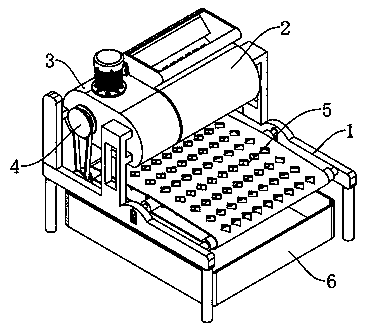
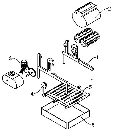
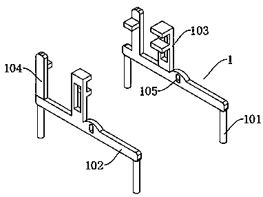
[0029] see Figure 1-5 , a crushing device for a waste sorting system, comprising a supporting mounting frame 1 and a linkage mechanism 4, characterized in that: the supporting mounting frame 1 includes a supporting foot 101, and the supporting foot 101 is fixedly connected with a horizontal mounting frame body 102, and the horizontal mounting frame The body 102 is fixedly connected with a first connecting frame body 103 and a second connecting frame body 104, and the middle position of the horizontal mounting frame body 102 is also provided with an installation groove 105; the first connecting frame body 103 and the second connecting frame body 104 are connected There is a garbage crushing mechanism 2 and a driving mechanism 3, the linkage mechanism 4 is connected with the driving mechanism 3, the lower end of the linkage mechanism 4 is connected with a transmission mechanism 5, the transmission mechanism 5 is installed on the horizontal installation frame body 102, and a coll...
Embodiment 2
[0036] see Image 6 , based on Embodiment 1, the difference is that;
[0037] The linkage mechanism 4 includes a first belt pulley 401 and a second belt pulley 402, the first belt pulley 401 is fixedly connected to the extended end of the first connection shaft 307, the second belt pulley 402 is connected to the transmission mechanism 5, and the first belt pulley A linkage belt 403 is connected around the disc 401 and the second belt disc 402 .
[0038] The transmission device 5 includes a first roller 501 and a second roller 502, both of which are rotatably connected to the horizontal mounting frame body 102, and one end of the first roller 501 close to the linkage mechanism 4 runs through the horizontal The mounting frame body 102 is fixedly connected with the second pulley 402 ; the first roller 501 and the second roller 502 are connected with a filter conveyor belt 503 , and the filter conveyor belt 503 is provided with a filter hole 504 .
[0039] The present invention ...
Embodiment 3
[0041] refer to Image 6 ; Based on Embodiment 1 or 2, the difference is that;
[0042] The transmission device 8 also includes an eccentric roller 505, the eccentric roller 505 is arranged between the first roller 501 and the second roller 502, the eccentric roller 505 is in contact with the inner wall of the filtering conveyor belt 503, and the eccentric roller 505 Mounting blocks 506 are fixedly installed at both ends, and the eccentric roller 505 is rotationally connected with the mounting block 506. Install on the groove 105.
[0043] The filter type conveyor belt 503 of the transmission mechanism 5 of the present invention is provided with a filter hole 504, and an eccentric roller 505 is rotated between the first roller 501 and the second roller 502 at the same time. During use, the filter type conveyor belt 503 and the eccentric roller The shafts 505 are in contact with each other, and the movement of the filter conveyor belt 503 can drive the eccentric roller 505 to...
PUM
 Abstract
Description
Claims
Application Information
 - R&D
- Intellectual Property
- Life Sciences
- Materials
- Tech Scout
- Unparalleled Data Quality
- Higher Quality Content
- 60% Fewer Hallucinations
Browse by: Latest US Patents, China's latest patents, Technical Efficacy Thesaurus, Application Domain, Technology Topic, Popular Technical Reports.
© 2025 PatSnap. All rights reserved.Legal|Privacy policy|Modern Slavery Act Transparency Statement|Sitemap|About US| Contact US: help@patsnap.com


