Rotational symmetrical and non-symmetrical plastic forming machine

A molding machine, plastic technology, used in forging presses, forging presses, transportation and packaging, etc., can solve problems such as difficult plastic molding

Active Publication Date: 2020-01-10
TUSAS MOTOR SANAYII ANONIM SIRKETI
View PDF11 Cites 0 Cited by
  • Summary
  • Abstract
  • Description
  • Claims
  • Application Information

AI Technical Summary

Problems solved by technology

Therefore, plastic molding is di

Method used


Image

  • Rotational symmetrical and non-symmetrical plastic forming machine
  • Rotational symmetrical and non-symmetrical plastic forming machine
  • Rotational symmetrical and non-symmetrical plastic forming machine

Examples


Embodiment Construction

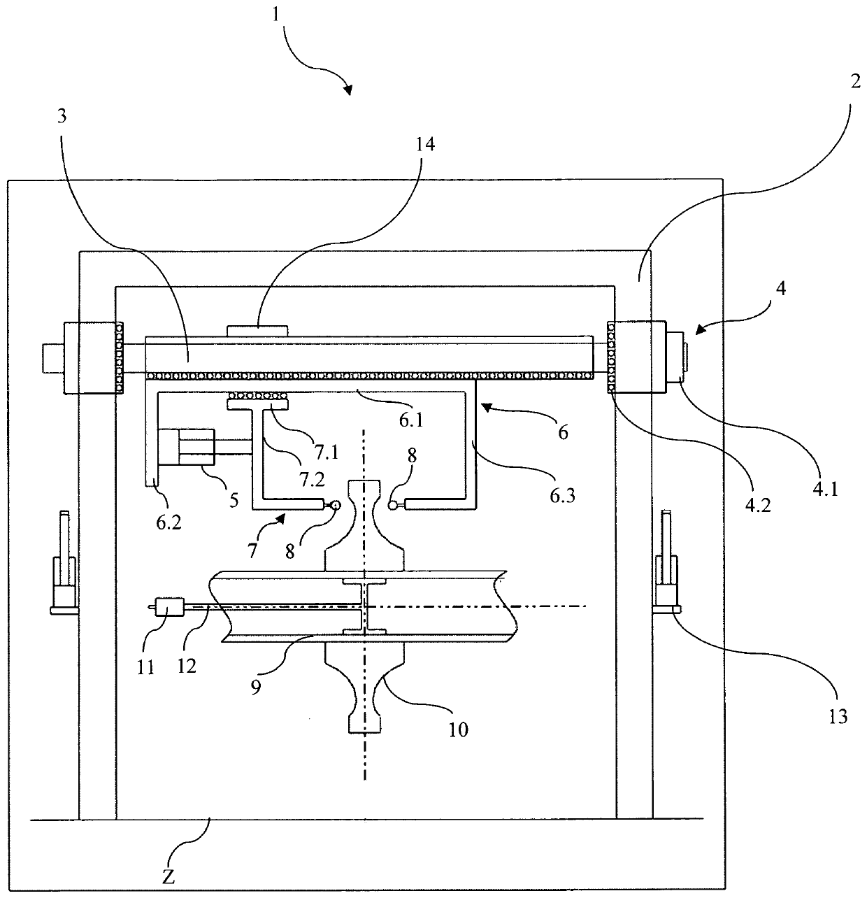
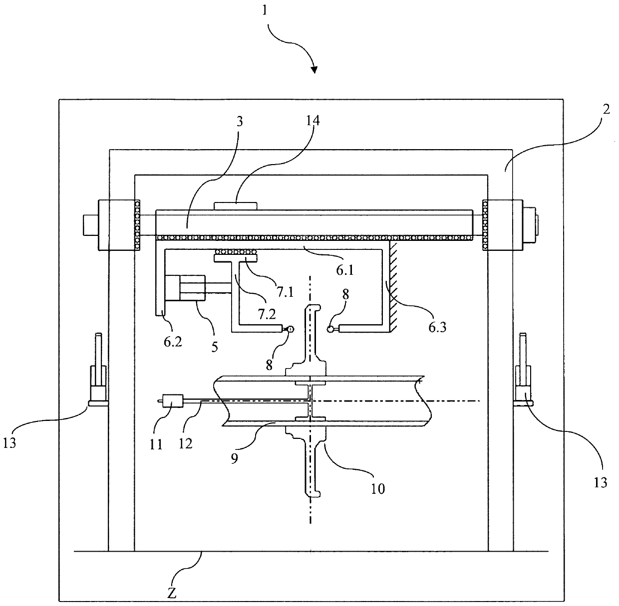
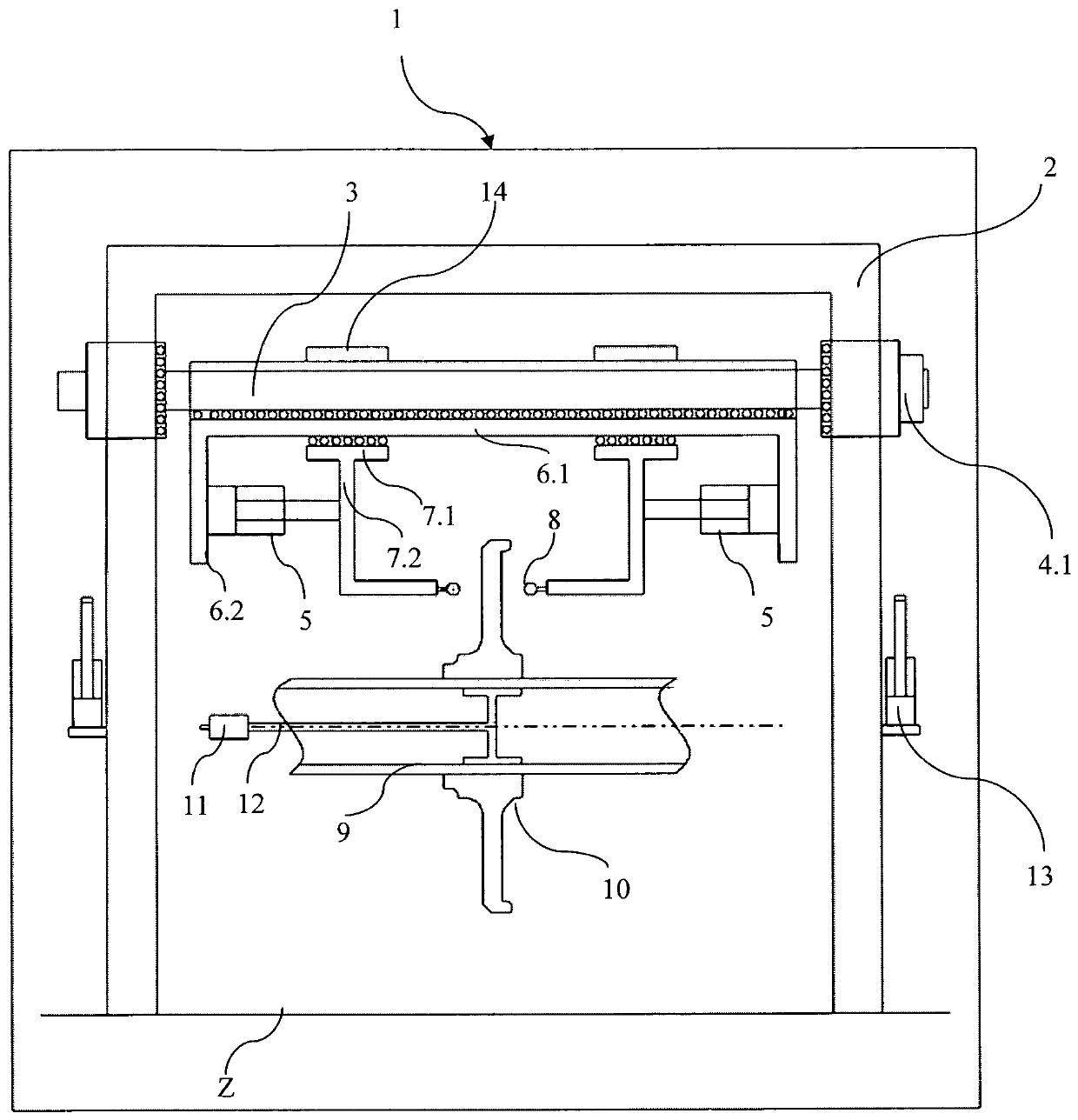
[0012] Components shown in the drawings are given reference numbers as follows:

[0013] 1. Plastic forming machine

[0014] 2. Fixed column

[0015] 3. Movable column

[0016] 4. Linear moving system

[0017] 4.1 Linear motor

[0018] 4.2 The first linear sliding bearing

[0019] 5. Actuator

[0020] 6. The first pressure rod

[0021] 6.1. First arm

[0022] 6.2. Second arm

[0023] 6.3. Third arm

[0024] 7. Second pressure rod

[0025] 7.1. Fourth arm

[0026] 7.2. Fifth arm

[0027] 8. Contact end

[0028] 9. Shaft

[0029] 10. Raw materials

[0030] 11. Electric motor

[0031] 12. Handle

[0032] 13. Stop piston

[0033] 14. The second linear sliding bearing

[0034] 15. Control system

[0035] Z. Ground

[0036] - a rotational plastic molding machine 1 for processing materials with a symmetrical or asymmetrical final geometry, essentially comprising at least one fixed column 2,

[0037] - a movable column 3 positioned such that the movable column wil...


PUM


Abstract

The invention relates to a plastic forming machine (1) including a fixed pole (2); a movable pole(3) that moves vertically; a shaft (9) for fixing a raw material on the shaft; an electric motor (5) for rotating the shaft; a linear movement system (4) enabling the movement of the movable pole (3); a first pressing rod (6) positioned on lower surface of the movable pole (3), includes a first arm (6.1) extending parallel to the movable pole, a second arm (6.2) extending vertical to the first arm, and a third arm (6.3), having a first end and second end, connected to the first arm from its secondend; a second pressing rod (7) having a first and a second end, is connected slidingly to the first arm from its first end; at least one actuator (5) connected to the first arm; a contact end (8) connected to the second ends of the second pressing rod (7) and the third arm (6.3); at least one control system (15) for controlling the linear movement mechanism (4) and the actuator (5).

Description

technical field [0001] The invention relates to the working principle of a machine for carrying out the method of plastic forming of metal raw materials. The present invention aims at forming the final geometry by continuous plastic shape change by applying hydraulic pressure from two directions in equal or different ratios on a stock rotating at a specific speed on a shaft (heated in thermal processing). Background technique [0002] The mold is used to obtain the desired geometry of the stock material to be machined in plastic forming machines known in the art. Tooling costs add to the overall cost. Also in these applications, intermediate products as symmetrical or asymmetrical forged parts cannot be produced in a single step. For this, more than one auxiliary device may be required. This increases the cost of intermediate products. Furthermore, in components obtained by conventional forging processes, the geometrical accuracy is low; the amount of material and the ti...

Claims


Application Information

Patent Timeline
IPC IPC(8): B21J9/02B21J9/10B21J13/00
CPCB21J9/02B21J9/10B21J13/00B21J5/06B21D22/18B21H1/04B21J5/04
Inventor M·F·阿克希特
Owner TUSAS MOTOR SANAYII ANONIM SIRKETI
Why Eureka
Try Eureka