
Automatic grinding rust removal device for steel pipe outer wall

A steel pipe, automatic technology, applied in the direction of grinding drive device, grinding machine, grinding frame, etc., can solve the problems of low rust removal efficiency, easy surface moisture, hidden dangers, etc., to achieve simple structure, reduce labor intensity, avoid channeling moving effect

Active Publication Date: 2020-01-10
SUZHOU ODIHUA ELECTRONIC CO LTD
View PDF6 Cites 25 Cited by
  • Summary
  • Abstract
  • Description
  • Claims
  • Application Information

AI Technical Summary

Problems solved by technology

[0003] During the long-term idle process of the steel pipes in the warehouse, the surface is prone to be affected by moisture to produce rust. When the steel pipes are used, the surface of the steel pipes needs to be derusted. Most of the derusting methods in the prior art are manually completed. For steel pipes with larger diameters, The method of manual rust removal is not only difficult to operate, low in efficiency of rust removal, but also has certain safety hazards

Method used


Image

  • Automatic grinding rust removal device for steel pipe outer wall
  • Automatic grinding rust removal device for steel pipe outer wall
  • Automatic grinding rust removal device for steel pipe outer wall

Examples


Embodiment 1

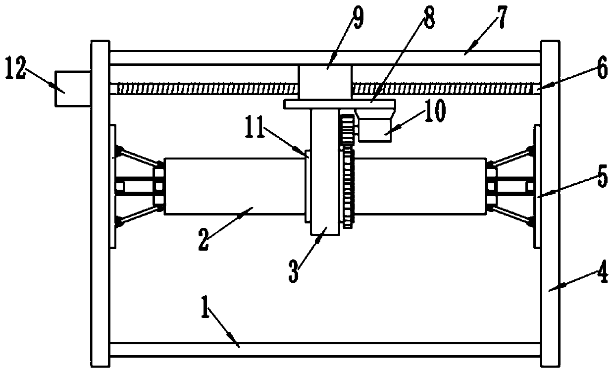
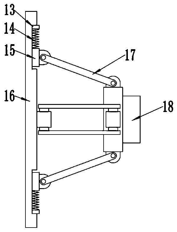
[0026] see Figure 1~3 , in an embodiment of the present invention, an automatic grinding and derusting device for the outer wall of a steel pipe includes a base 1, a grinding mechanism 3 and a fixing mechanism 5; A top plate 7 is fixedly installed on the top of the top plate 7, and a first screw rod 6 is arranged below the top plate 7. The left and right sides of the first screw rod 6 are respectively rotatably connected with two side plates 4, and the first screw rod 6 is threadedly connected with a first screw sleeve. 9. The upper side of the first screw sleeve 9 is slidingly connected with the top plate 7, and the rotation of the first screw rod 6 drives the first screw sleeve 9 to slide left and right at the bottom of the top plate 7;

[0027] Specifically, in this embodiment, the outer side of the side plate 4 is fixedly installed with a first rotating motor 12 that drives the first screw rod 6 to rotate;

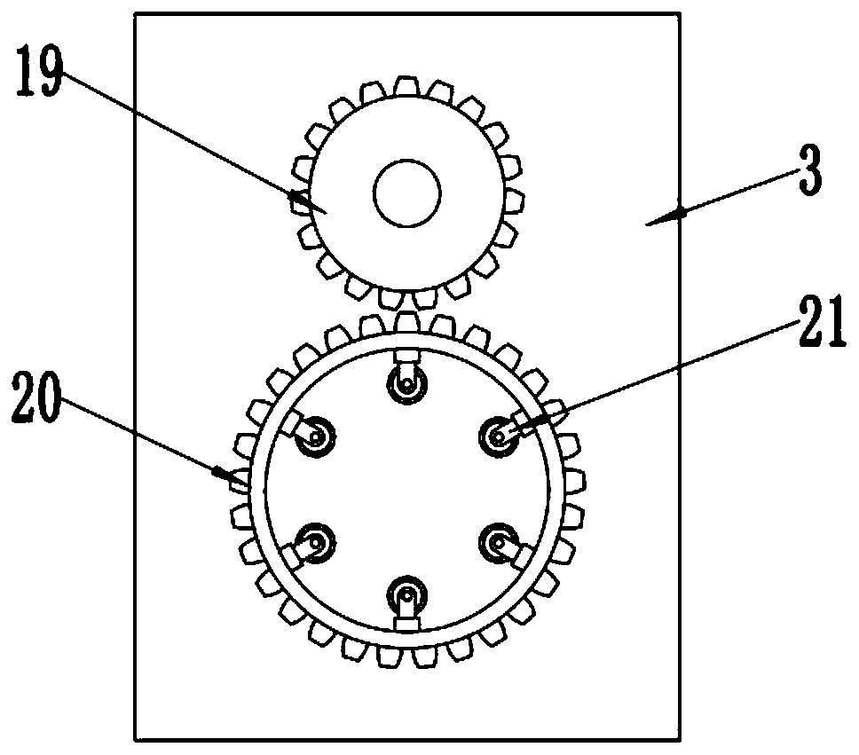
[0028] The grinding mechanism 3 is fixedly installed under the ...

Embodiment 2

[0032] see Figure 1~3 , in an embodiment of the present invention, an automatic grinding and derusting device for the outer wall of a steel pipe includes a base 1, a grinding mechanism 3 and a fixing mechanism 5; A top plate 7 is fixedly installed on the top of the top plate 7, and a first screw rod 6 is arranged below the top plate 7. The left and right sides of the first screw rod 6 are respectively rotatably connected with two side plates 4, and the first screw rod 6 is threadedly connected with a first screw sleeve. 9. The upper side of the first screw sleeve 9 is slidingly connected with the top plate 7, and the rotation of the first screw rod 6 drives the first screw sleeve 9 to slide left and right at the bottom of the top plate 7;

[0033] Specifically, in this embodiment, the outer side of the side plate 4 is fixedly installed with a first rotating motor 12 that drives the first screw rod 6 to rotate;

[0034]The grinding mechanism 3 is fixedly installed under the f...


PUM


Abstract

The invention relates to the technical field of steel pipe machining, in particular to an automatic grinding rust removal device for a steel pipe outer wall. The device comprises a base, a grinding mechanism and a fixing mechanism. Two side plates are symmetrically and fixedly mounted on the left side and the right side of the base, a top plate is fixedly mounted on the tops of the side plates, afirst screw rod is arranged below the top plate, a first screw sleeve is in threaded connection to the first screw rod, the grinding mechanism is fixedly mounted below the first screw sleeve through amounting plate, the interior of the grinding mechanism is rotatably provided with a rotating sleeve, the rotating sleeve is of a sleeve structure with openings in the two ends, the outer side of therotating sleeve is fixedly provided with a gear ring, a round gear is rotatably mounted on the grinding mechanism, and the round gear is engaged with the gear ring. The rotating sleeve is arranged onthe outer side of a steel pipe in a sleeving manner, the first screw sleeve which continuously moves left and right drives the rotating sleeve to move left and right on the outer side of the steel pipe, a grinding roller makes sufficient contact with all portions of the surface of the steel pipe, and the steel pipe can be effectively ground.

Description

technical field [0001] The invention relates to the technical field of steel pipe processing, in particular to an automatic grinding and derusting device for the outer wall of a steel pipe. Background technique [0002] Steel pipes are used to transport fluids and powdery solids, exchange heat, and manufacture mechanical parts and containers. It is also a kind of economical steel. The development of steel pipe production technology began with the rise of the bicycle manufacturing industry, the development of petroleum in the early 19th century, the manufacture of ships, boilers, and aircraft during the two world wars, the manufacture of thermal power boilers after the Second World War, the development of the chemical industry and Drilling, production and transportation of oil and natural gas have strongly promoted the development of steel pipe industry in terms of variety, output and quality. [0003] During the long-term idle process of the steel pipes in the warehouse, th...

Claims


Application Information

Patent Timeline
IPC IPC(8): B24B27/033B24B41/02B24B41/06B24B47/04
CPCB24B27/033B24B41/02B24B41/06B24B47/04
Inventor 费城
Owner SUZHOU ODIHUA ELECTRONIC CO LTD
Features
  • Generate Ideas
  • Intellectual Property
  • Life Sciences
  • Materials
  • Tech Scout
  • Unparalleled Data Quality
  • Higher Quality Content
  • 60% Fewer Hallucinations
Learn More