Measuring ruler for ultrasonic detection of defects

An ultrasonic and defect technology, which is used in the analysis of solids using sound waves/ultrasonic waves/infrasonic waves, material analysis using sound waves/ultrasonic waves/infrasonic waves, and measuring devices. It can solve the problem that there is no corresponding interface between the ruler and the probe, and the angle of the ruler cannot be fixed accurately , There is no fixed base point for the ruler, etc., to improve the detection accuracy and accuracy, save labor costs, and increase repeatability

Active Publication Date: 2020-01-10
SHANDONG MECHANICAL ENG TESTING CO LTD
View PDF8 Cites 1 Cited by
  • Summary
  • Abstract
  • Description
  • Claims
  • Application Information

AI Technical Summary

Problems solved by technology

[0003] At present, there are mainly the following disadvantages in the determination of steel ruler defects: 1) There is no corresponding interface between the ruler and the probe, and there is no fixed base point for the placement of the ruler when calibrating the probe and actually
Increased error; 2) When the probe is obliquely parallel to scan, the angle of the ruler cannot be fixed accurately, and the measurement error of the defect is relatively large; 3) When the probe moves, the steel ruler is difficult to operate, and the steel ruler is seriously reduced. 4) When inspecting on the upside, the line of sight is blocked, and it is difficult to place a steel ruler when marking defects
When recording defects, it is impossible to achieve single-person operation and needs assistance; 5) When detecting large pipelines, the measuring range of the ruler is often insufficient, and the secondary measurement increases the error value: 6) When the workpiece is a cylindrical or circular weld, If the curvature is small, the steel ruler cannot determine the circumferential position of the defect

Method used


Image

  • Measuring ruler for ultrasonic detection of defects
  • Measuring ruler for ultrasonic detection of defects
  • Measuring ruler for ultrasonic detection of defects

Examples


Embodiment Construction

[0037] The present invention will be specifically described below in conjunction with the accompanying drawings and embodiments.

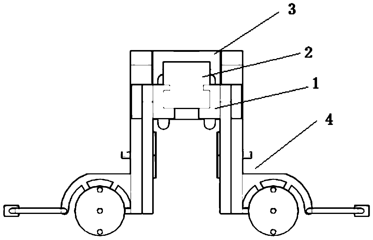
[0038] figure 1 Shown is a schematic front view of the structure of the present invention.

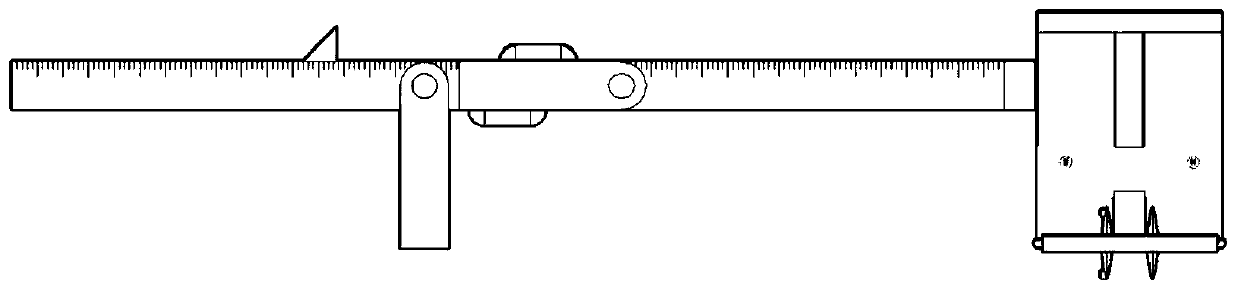
[0039] figure 2 Shown is a schematic side view of the structure of the present invention.

[0040] The present invention provides an ultrasonic detection defect measuring ruler, which includes four parts: a sliding track 1, a photoelectric device 2, a clamping device 3 and a counting roller 4, wherein:

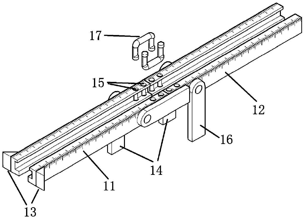
[0041] Described sliding track 1 is used for defining direction, comprises slideway body 11 and track lengthening part 12 (such as image 3 shown);

[0042] Described optoelectronic device 2 is used for positioning, comprises laser head 21, dichroic prism 22 and liquid crystal display module 23 (as Figure 4 shown);

[0043] The clamping device 3 is used to clamp the probe, and includes a pair of symmetrical splints 31, and the two splints are rigidl...


PUM


Abstract

The invention discloses a measuring ruler for ultrasonic detection of defects, and the measuring ruler comprises a sliding rail, a photoelectric device, a clamping device and a counting roller; the sliding rail is used for limiting the direction and comprises a slideway body and a rail lengthening part; the photoelectric device is used for positioning and comprises a laser head, a beam splitter prism and a liquid crystal display module; the clamping device is used for clamping a probe and comprises a pair of symmetrical clamping plates, and the two clamping plates are rigidly connected into anintegral structure through a connecting part. The counting roller is used for measuring the length and comprises two roller frames arranged on the opposite sides, and the two sides of each roller frame are each provided with two rollers. The probe and the straight ruler are fixed through a groove, so the problem that a measurement base point is inaccurate is solved; the defect position is determined through laser and the sliding rail, and the detection precision and accuracy are greatly improved. The permanent magnets are arranged at multiple positions, and the probe and the measuring ruler can be fixed to a workpiece, thereby facilitating the detection operation, and reducing the manual assistance.

Description

technical field [0001] The invention relates to a measurement and positioning device for ultrasonic detection of defects, in particular to an ultrasonic detection for welding seams, which belongs to the field of non-destructive testing. Background technique [0002] Ultrasonic testing is one of the most commonly used non-destructive testing methods. A-type pulsed ultrasonic testing is widely used in energy and power, petrochemical, railway, shipbuilding, and machinery due to its advantages of portable equipment, simple operation, high detection rate, and low cost. Manufacturing and other industries. During the ultrasonic inspection of the inclined probe, the defect is scanned by the ultrasonic waves emitted by the inclined probe; after the detector obtains the signal of the reflected wave of the defect, it uses the probe as a reference to locate the defect and measure the length with an ordinary steel ruler; then the workpiece Defects in the quality classification. It main...

Claims


Application Information

Patent Timeline
Patent Type & Authority Applications(China)
IPC IPC(8): G01N29/04G01N29/22G01N29/265G01B5/02
CPCG01N29/04G01N29/048G01N29/22G01N29/265G01B5/02
Inventor 韦鸿起齐高君岳大庆丁成海
Owner SHANDONG MECHANICAL ENG TESTING CO LTD
Why Eureka
Try Eureka