Magnetic field aggregation component and non-contact leakage current measurement device and method
A technology of magnetic field gathering and measuring device, applied in measuring device, measuring electrical variable, magnitude/direction of magnetic field, etc., can solve the problems of complicated signal processing steps, high production cost, poor measurement accuracy, etc.
- Summary
- Abstract
- Description
- Claims
- Application Information
AI Technical Summary
Problems solved by technology
Method used
Image
Examples
Embodiment 1
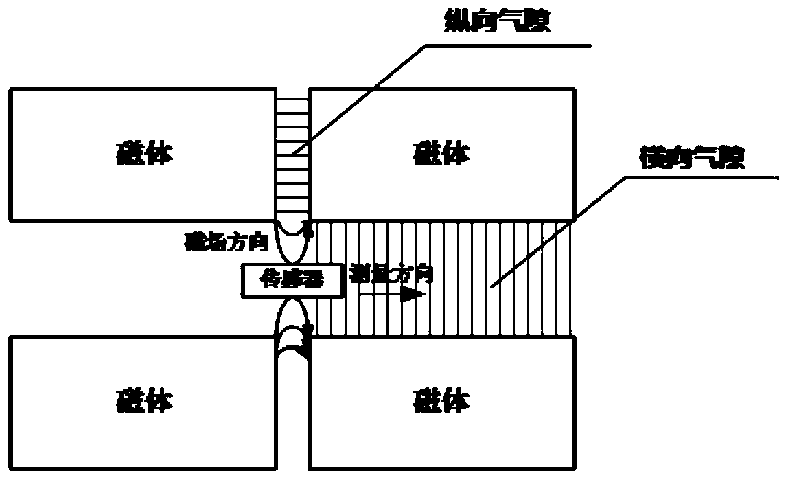
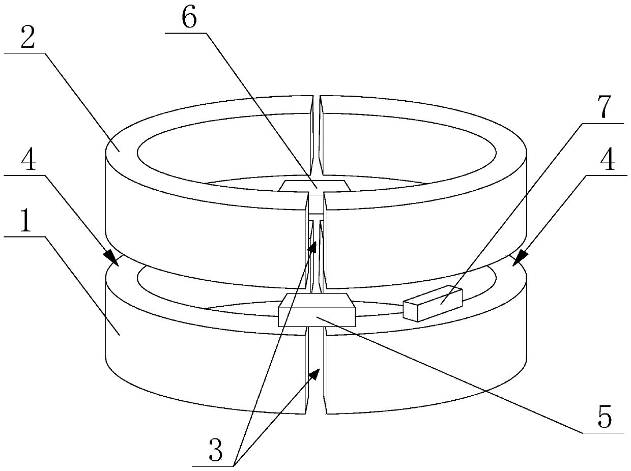
[0083] like figure 2 As shown in the magnetic field concentrator, its magnetic field concentrator includes a first magnetic field concentrator 1, and a second magnetic field concentrator 2 located above the first magnetic field concentrator 1, on the first magnetic field concentrator 1 and the second magnetic field concentrator 2 Each is provided with two longitudinal air gaps 3, and the two longitudinal air gaps 3 are arranged symmetrically about the central axis of the magnetic field concentrator, and a transverse air gap 4 is arranged between the first magnetic field concentrator 1 and the second magnetic field concentrator 2; the first The longitudinal air gap 3 of the magnetic field concentrator 1 is aligned with the longitudinal air gap 3 of the second magnetic field concentrator 2 .
[0084] like figure 1 and figure 2As shown, at this time, the first magnetic field sensor 5 and the second magnetic field sensor 6 are respectively located between the longitudinal air ...
Embodiment 2
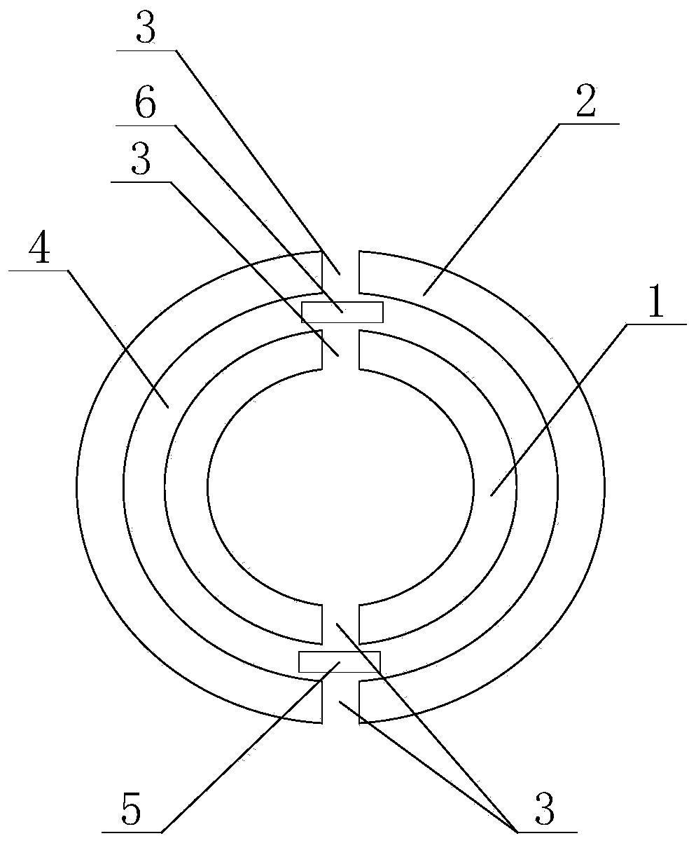
[0093] like image 3 As shown, another magnetic field concentrator of the present invention includes a first magnetic field concentrator 1, and a second magnetic field concentrator 2 located outside the first magnetic field concentrator 1, the first magnetic field concentrator 1, the second magnetic field concentrator Two longitudinal air gaps 3 are respectively arranged on the device 2, and the two longitudinal air gaps 3 are arranged symmetrically with respect to the central axis of the magnetic field concentrator, and a horizontal air gap is arranged between the first magnetic field concentrator 1 and the second magnetic field concentrator 2. Gap 4.
[0094] In some embodiments, the width of the transverse air gap 4 is not greater than 5 mm, and the width of the longitudinal air gap 3 is not greater than 1 mm.
[0095] In some embodiments, the measuring direction of the magnetic field sensor is placed parallel to the direction of the measured magnetic field to further incr...
Embodiment 3
[0098] A non-contact leakage current measuring device, comprising a housing 8, a first magnetic field concentrator 1, a first magnetic sensor 5, a second magnetic sensor 6 and a signal processing circuit are arranged in the housing 8, and a signal processing circuit is also arranged in the housing 8 A second magnetic field concentrator 2 and a partition 9 are provided, and the partition 9 is used to separate the first magnetic field concentrator 1 and the second magnetic field concentrator 2, and the first magnetic field concentrator 1 and the second magnetic field concentrator 2 Concentric arrangement, the first magnetic field concentrator 1 and the second magnetic field concentrator 2 are respectively provided with two longitudinal air gaps 3, and a transverse air gap 4 is arranged between the first magnetic field concentrator 1 and the second magnetic field concentrator 2, so The first magnetic sensor 5, the second magnetic sensor 6 and the signal processing circuit are loca...
PUM
 Abstract
Description
Claims
Application Information
 - R&D
- Intellectual Property
- Life Sciences
- Materials
- Tech Scout
- Unparalleled Data Quality
- Higher Quality Content
- 60% Fewer Hallucinations
Browse by: Latest US Patents, China's latest patents, Technical Efficacy Thesaurus, Application Domain, Technology Topic, Popular Technical Reports.
© 2025 PatSnap. All rights reserved.Legal|Privacy policy|Modern Slavery Act Transparency Statement|Sitemap|About US| Contact US: help@patsnap.com


