Backlight module

A backlight module and blue light technology, applied in the field of backlight, can solve the problems of unfavorable energy saving advantages, low transmittance of the diffuser, uneven brightness of the surface light source, etc.

Inactive Publication Date: 2020-01-10
WUHAN CHINA STAR OPTOELECTRONICS TECH CO LTD
View PDF4 Cites 4 Cited by
  • Summary
  • Abstract
  • Description
  • Claims
  • Application Information

AI Technical Summary

Problems solved by technology

[0003] However, due to the limitation of the light-emitting angle of the chip and the limitation of the number of chips, the surface light source has the problem of uneven brightness across the entire surface.
Uniform light mixing can be achieved by adding a high-haze diffuser, but due to the low transmittance of the diffuser, it is easy to reduce the front brightness of the surface light source, which is not conducive to the embodiment of energy saving advantages
If the mixing effect is improved by increasing the light-emitting angle of the chip, the increase in the light-emitting angle of the chip will also reduce the luminous efficiency of the chip, and the overall light energy utilization rate of the surface light source will also deteriorate
In addition, if the surface microstructure technology is used to achieve uniform light mixing, it will not only increase the sample manufacturing process, but also increase the production cost, and the stability of the process is not mature, so it is not an ideal light mixing solution.

Method used


Image

  • Backlight module
  • Backlight module
  • Backlight module

Examples


Embodiment Construction

[0022] The following will clearly and completely describe the technical solutions in the embodiments of the present invention with reference to the drawings in the embodiments of the present invention. Apparently, the described embodiments are only some of the embodiments of the present invention, but not all of them. Based on the embodiments of the present invention, all other embodiments obtained by those skilled in the art without creative efforts fall within the protection scope of the present invention.

[0023] The terms "first", "second", "third", etc. (if any) in the description and claims of the present invention and the above drawings are used to distinguish similar objects and not necessarily to describe a specific order or sequentially. It should be understood that the items so described are interchangeable under appropriate circumstances. Furthermore, the terms "comprising" and "having", as well as any variations thereof, are intended to cover a non-exclusive in...


PUM

PropertyMeasurementUnit
thicknessaaaaaaaaaa
heightaaaaaaaaaa

Abstract

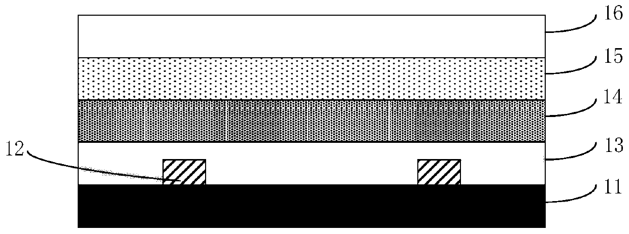
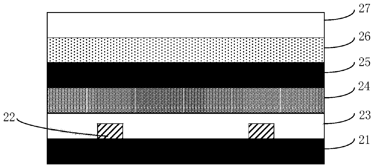
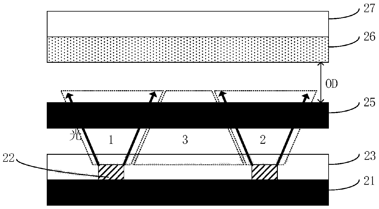
The present invention discloses a backlight module. According to the backlight module, a semi-transparent diaphragm layer is used in a miniLED structure to weaken luminance in a positive view angle ofa chip, and luminous intensity between chips is increased, so that light mixing uniformity of an entire panel of the miniLED structure is improved, to prepare a backlight module of an ultrathin liquid crystal display panel.

Description

technical field [0001] The invention belongs to the field of backlight technology, in particular to a backlight module. Background technique [0002] The sub-millimeter light-emitting diode (mini Light Emitting Diode, miniLED) has become a hot spot in the market development. It has many advantages such as thinness, power saving, flexibility and bendability, high brightness, and the ability to produce narrow-frame full-screen display devices and high dynamic contrast display devices. , has become the focus of market attention. [0003] However, due to the limitation of the light-emitting angle of the chip and the limitation of the number of chips, the surface light source has the problem of uneven brightness across the entire surface. Uniform light mixing can be achieved by adding a high-haze diffuser, but due to the low transmittance of the diffuser, it is easy to reduce the front brightness of the surface light source, which is not conducive to the embodiment of energy sav...

Claims


Application Information

Patent Timeline
Patent Type & Authority Applications(China)
IPC IPC(8): G02F1/13357
CPCG02F1/133603G02F1/133611G02F1/133614G02F1/133606G02F1/133609G02F1/133607
Inventor 杨勇
Owner WUHAN CHINA STAR OPTOELECTRONICS TECH CO LTD
Why Eureka
Try Eureka