
Surface-mounted inductor with composite structure and manufacturing method of surface-mounted inductor

A surface-mounted, composite structure technology, applied in the direction of inductance/transformer/magnet manufacturing, inductors, fixed inductors, etc., can solve the problems of exposed magnetic flux leakage of the coil, unbalanced body left and right, and unfixable coil position. Achieve the effects of increasing the area ratio, reducing leakage flux, and low manufacturing cost

Pending Publication Date: 2020-01-10
汕头市信技电子科技有限公司
View PDF0 Cites 1 Cited by
  • Summary
  • Abstract
  • Description
  • Claims
  • Application Information

AI Technical Summary

Problems solved by technology

Although this method can ensure that the position of the coil is centered, since the formed E-shaped plate needs to maintain its wrapping and durability, its outer wall thickness needs to be at least 0.1 to 0.15mm or even larger. If the size of the surface mount inductor is larger Small, the fact that cannot be ignored is that the outer wall of the E-type plate cannot be reduced, so the built-in coil can only be reduced, and the Rdc value cannot be reduced;
[0004] Another example is the patent document: Japanese Patent No. 6060116, which discloses a manufacturing method using a flat plate, which uses a flat plate instead of an E-shaped flat plate to increase the size of the built-in coil, but this method is difficult when molding in a mold. , the position of the coil cannot be fixed, the formed blank has left-right imbalance, the coil is exposed and produces more leakage flux problems, and the final product cannot achieve the best consistency

Method used


Image

  • Surface-mounted inductor with composite structure and manufacturing method of surface-mounted inductor
  • Surface-mounted inductor with composite structure and manufacturing method of surface-mounted inductor

Examples


Embodiment Construction

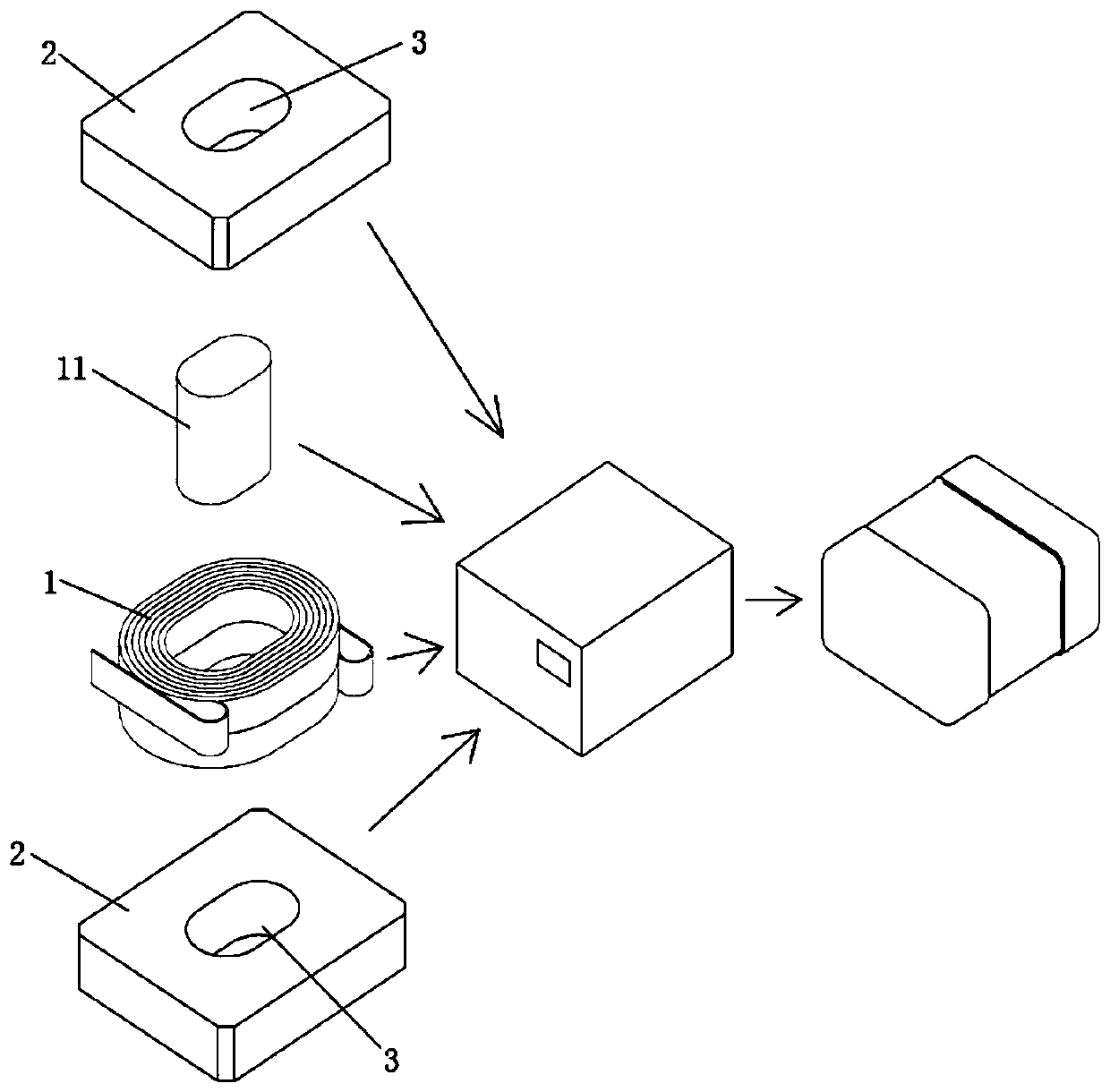
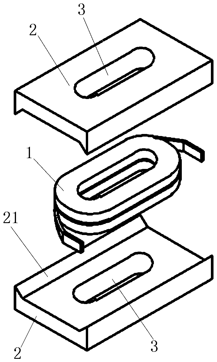
[0021] see figure 1 , figure 2 As shown, it is a structural schematic diagram of a preferred embodiment of the present invention. The present invention is a surface mount inductor with a composite structure, which has a built-in coil 1, a central column 11, and two sets of pressure plate main bodies 2, and the density of the central column 11 It is higher than the density of the main body 2 of the pressing plate, preferably the density of the center column 11 is more than twice the density of the main body 2 of the pressing plate. Through the independently arranged high-density central pillars 11, the magnetic permeability can be improved, and the electrical characteristics can be improved while reducing the overall size of the inductor.

[0022] The specific structure is that the main body 2 of the pressing plate is in the shape of a plate, and the center of the main body 2 of the pressing plate is provided with a track-shaped hole 3, the hole 3 of the main body 2 of the pr...


PUM

PropertyMeasurementUnit
Lengthaaaaaaaaaa

Abstract

The invention relates to a surface-mounted inductor with a composite structure and a manufacturing method of the surface-mounted inductor. The surface-mounted inductor is provided with a built-in coil, a middle column and two sets of pressing plate main bodies; the density of the middle column is higher than that of the pressing plate main bodies; the pressing plate main bodies are plate-shaped; and runway-shaped hole sites are formed in the centers of the pressing plate main bodies. During molding, the structure of the surface-mounted inductor is distributed in the following manners that: thetwo sets of pressing plate main bodies are distributed above and below the built-in coil respectively; the middle column penetrates through the center of the built-in coil; the upper end and the lower end of the middle column are correspondingly inserted into the hole sites of the pressing plate main bodies respectively; and the two pressing plate main bodies wrap the built-in coil through the pressing of a mold, so that the two pressing plate main bodies and the built-in coil can be integrally molded to form a blank. According to the inductor manufactured through the method, the covering performance of the blank is good; the leakage flux of the inductor hardly exists; the size of the coil can be increased to the maximum extent; Isat is increased; Rdc is reduced; the high-density independent middle column is adopted, and the pressing plate main bodies are properly shaped, so that magnetic permeability can be increased; damage to the pressing plate main bodies is reduced; and the sizeof the inductor is reduced.

Description

technical field [0001] The invention belongs to the technical field of manufacturing surface mounting inductors, in particular to a surface mounting inductor with a composite structure and a manufacturing method thereof. Background technique [0002] At present, the industry has widely used magnetic powder and resin-made sealing materials to form coil surface-mounted inductors. This field emphasizes the Isat value of the DC superimposed current and the Rdc value of the DC resistance, and the higher the Isat value, the higher the Isat value. A lower Rdc value is required, therefore, on the premise of a small size, it is necessary to increase the size of the built-in coil while reducing the leakage flux. [0003] Such as the patent document: Japanese Patent No. 4714779, which discloses a manufacturing method using an E-shaped tablet. This surface mount inductor places a coil formed by winding copper wires on an E-shaped plate, and places both ends of the coil Placed on the ou...

Claims


Application Information

Patent Timeline
IPC IPC(8): H01F17/04H01F27/255H01F27/29H01F41/00H01F41/02
CPCH01F17/045H01F27/255H01F27/29H01F41/00H01F41/02
Inventor 庄仲郑王丹娜
Owner 汕头市信技电子科技有限公司
Learn More