Manufacturing process of IBC battery assembly

CN110676336AActive Publication Date: 2020-01-10SUZHOU AUTOWAY SYST

Image

  • Manufacturing process of IBC battery assembly
  • Manufacturing process of IBC battery assembly
  • Manufacturing process of IBC battery assembly

Examples


Embodiment Construction

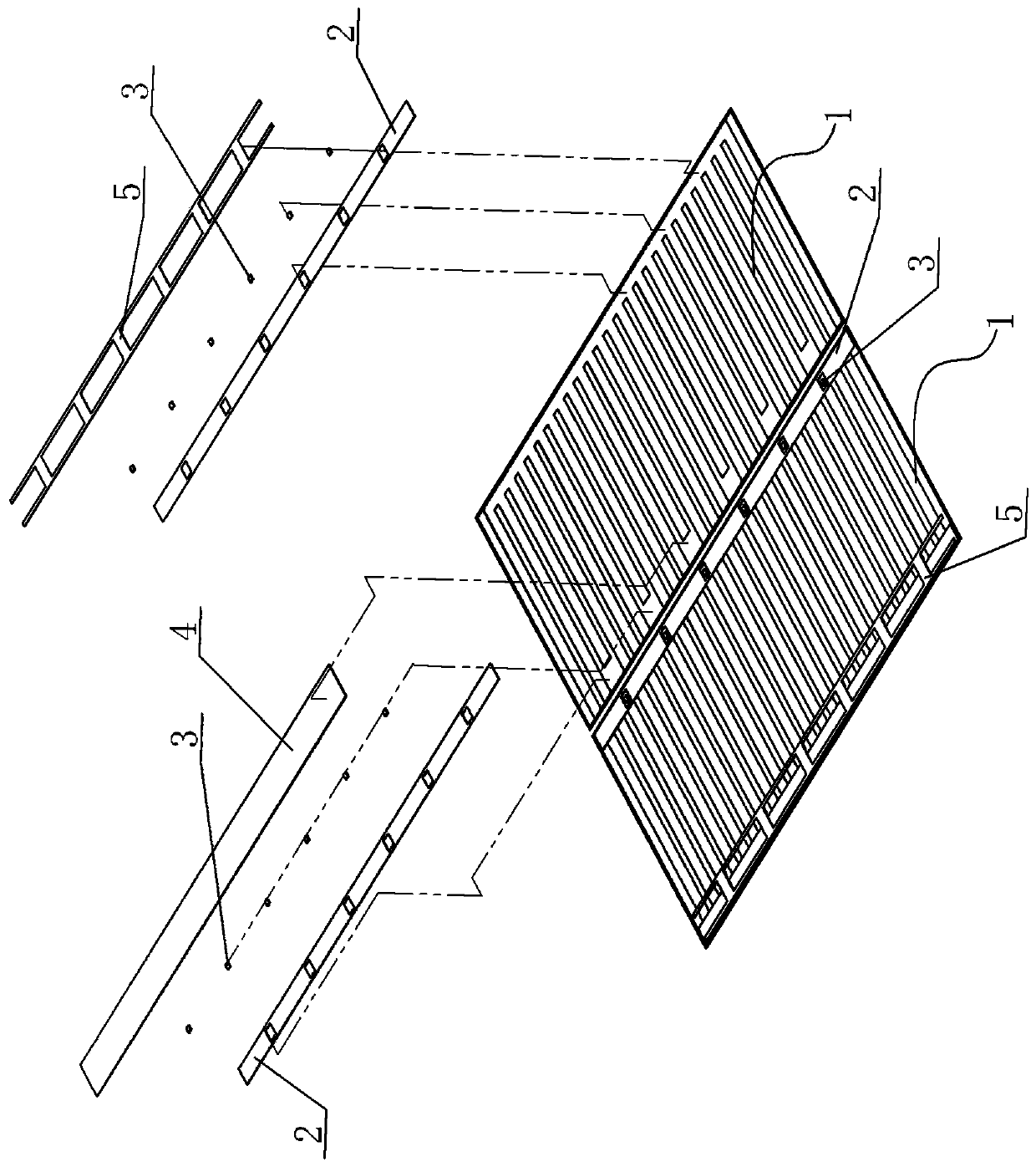
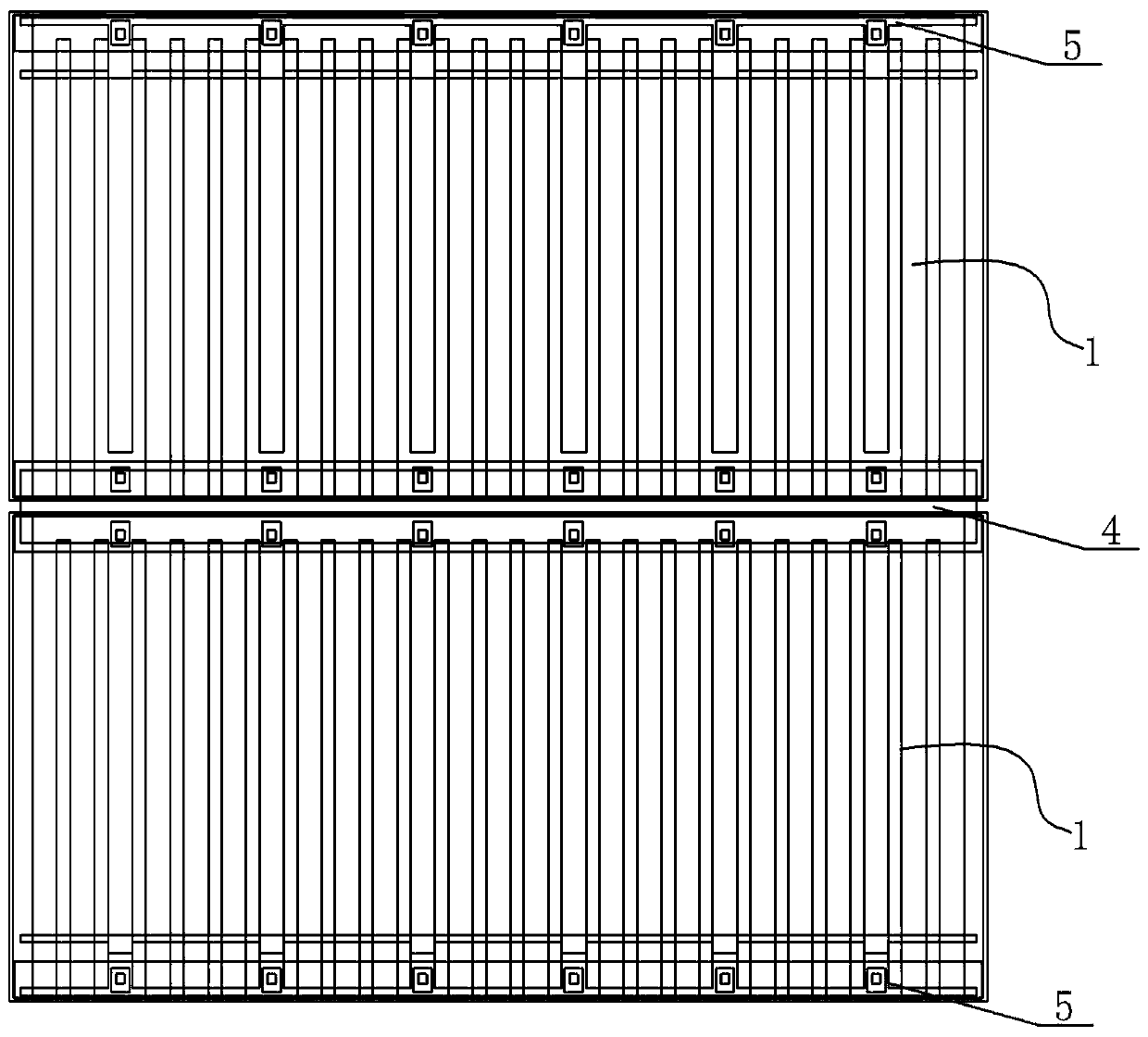
[0038] A kind of manufacturing process of IBC battery assembly, see Figure 1-Figure 2 , and its specific process steps include the following two types:

[0039] Option A:

[0040] S1. Laser cutting: First, laser cut the entire cell, and form (n-1) laser scratches on the cell, so that the cell is divided into n small cells 1;

[0041] S2. Coating insulating glue: Preset a certain number of lead-out electrodes on the two sides of n small battery pieces 1 arranged along the length direction, and apply insulating glue 2 on the outer periphery of the lead-out electrodes at the same time;

[0042] S3. Curing the insulating glue: curing the battery sheet coated with the insulating glue 2;

[0043] S4. Coating solder paste: coating the solder paste 3 on the positions corresponding to the preset lead-out electrodes on n pieces of small cells 1;

[0044] S5, arranging sheets: arranging n pieces of small cells 1 according to positive and negative series connection;

[0045] S6. Plac...


PUM


Abstract

The invention provides a manufacturing process of an IBC battery assembly. The manufacturing process improves the assembly efficiency of the battery assembly, ensures the yield and further ensures thepower generation efficiency of IBC battery pieces. The process comprises the following specific steps: S1,carrying out laser cutting: firstly, carrying out laser cutting on a whole battery piece, andforming (n-1) laser scratches on the battery piece to make the battery piece divided into n small battery pieces; S2, coating insulating glue : presetting a certain number of extraction electrodes onareas arranged along the length direction at the two sides of each of the n small battery pieces, and meanwhile, coating the peripheries of the extraction electrodes with insulating glue; S3, curingthe insulating glue: curing the battery pieces coated with the insulating glue; S4, coating solder paste: coating the solder paste at the positions of the corresponding preset extraction electrodes onthe small battery pieces; S5, arranging the battery pieces: arranging the small battery pieces in a positive-negative series connection manner; S6, placing a series solder strip; and S7, welding thesolder strip: welding the solder strip and the solder paste at the corresponding positions to conduct the solder strip and the solder paste.

Description

technical field [0001] The invention relates to the technical field of manufacturing IBC battery components, in particular to a manufacturing process of IBC battery components. Background technique [0002] IBC batteries do not have metal electrodes on the light-receiving side of the battery, which can completely eliminate the optical loss on the front side and increase the short-circuit current. All electrodes are distributed on the back of the battery in a cross-fingered manner. The larger metallization area improves the battery fill factor. A good passivation process can increase the open circuit voltage of the battery. [0003] After the cells are serially fabricated into modules, a complete solar cell panel can finally be obtained. Because in the process of connecting the cells in series, the cells need to be connected with ribbons, and the resistance (R) of the ribbon itself will cause a loss of electrical performance. Therefore, how to improve the power generation ef...

Claims


Application Information

Patent Timeline
10 Jan 2020
Publication
CN110676336A
IPC
H01L31/048; H01L31/18
CPC
H01L31/048; H01L31/0481; H01L31/188; Y02E10/50
Inventors
鲁乾坤; 彭刘辉