Battery anti-loosening wiring device used for new energy automobile

A new energy vehicle and wiring device technology, which is applied to the parts of the connecting device, the device for joining/disconnecting the connecting parts, the coupling device, etc., can solve the problems of loose wiring, potential fire hazards, and electric sparks, etc., and achieve tight connection solid effect

Active Publication Date: 2020-01-10
JIANGSU HUAZI AUTO INDUSTRY CO LTD
View PDF5 Cites 6 Cited by
  • Summary
  • Abstract
  • Description
  • Claims
  • Application Information

AI Technical Summary

Problems solved by technology

[0004] If the battery terminals or the external wiring are loose, it will cause electric sparks, which may cause a fire hazard
During the driving process of the car, the battery connection is often in a bumpy state, and the connection is likely to be loose, and the higher the speed, the more likely to generate high-frequency vibration. The conventional bolt and screw connection structure is likely to move along the contact surface under high-frequency vibration Slip in the loose direction, resulting in poor contact, and for the most important connection between the battery module and the outside world, it is often necessary to use quick-plug and quick-release wiring to facilitate the quick disconnection of the electrical connection when repairing or replacing the battery module, otherwise It is very troublesome to remove a lot of bolts to take out the battery module. The quick plug and quick release is generally in the form of a plug and socket. This wiring method does not have any fastening and is prone to loosening.

Method used


Image

  • Battery anti-loosening wiring device used for new energy automobile
  • Battery anti-loosening wiring device used for new energy automobile
  • Battery anti-loosening wiring device used for new energy automobile

Examples


Embodiment Construction

[0031] The following will clearly and completely describe the technical solutions in the embodiments of the present invention with reference to the accompanying drawings in the embodiments of the present invention. Obviously, the described embodiments are only some, not all, embodiments of the present invention. Based on the embodiments of the present invention, all other embodiments obtained by persons of ordinary skill in the art without making creative efforts belong to the protection scope of the present invention.

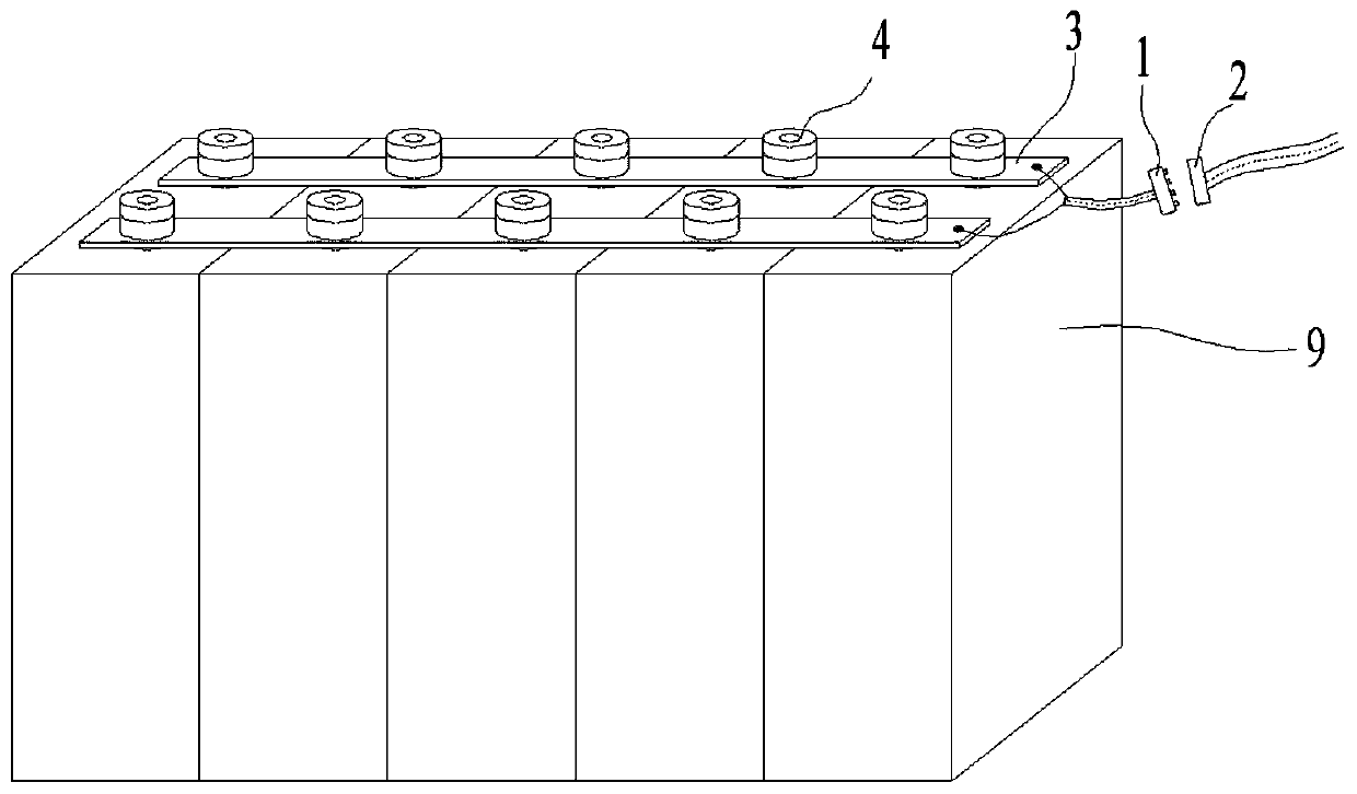
[0032] Such as figure 1 As shown, a battery anti-loosening device for new energy vehicles includes a first joint 1, a second joint 2 and a wire 5, the first joint 1 is connected to the battery module 9 through the wire 5, the first joint 1 and the second joint 2 The electrical connection is made in the form of plug-in or plug-in.

[0033] The external wiring of the battery module 9 uses the first connector 1 and the second connector 2 as interfaces, the first c...


PUM


Abstract

The invention discloses a battery anti-loosening wiring device used for a new energy automobile. The device comprises a first connector, a second connector and a lead. The first connector is connectedwith a battery module through the lead, and the first connector and the second connector are electrically connected in an inserted mode or a plug-in mode. The first connector comprises a first plastic block, first interfaces and an induction column. The second connector comprises a second plastic block, second interfaces and an armature. The induction column is glued in the first plastic block, one end of the induction column is exposed out of the first plastic block, the first interfaces are arranged in a side surface of the first plastic block and are located on the same side as an end portion, exposed out of the first plastic block, of the induction column, the two first interfaces are connected with an anode and a cathode of the battery module through leads, and the leads spirally wind the induction column in the first plastic block. One side of the second plastic block is provided with a jack and the two second interfaces, the second interfaces are in butt joint with the first interfaces, the armature is embedded in the jack, the jack is in butt joint with the induction column, the lead is glued in the second plastic block, and the second interfaces are connected with the leads.

Description

technical field [0001] The invention relates to the field of auto parts, in particular to a battery anti-loosening wiring device for new energy vehicles. Background technique [0002] New energy vehicles use power batteries as their power source, and power batteries are often installed inside the car in the form of modules, mostly on the chassis of the car. [0003] All electrical equipment inside the car obtains power from the battery module. The battery module is generally a plurality of single batteries connected to each other to form a module, and then powered externally as a whole. The battery module needs to use connectors for electrical wiring when it supplies power to the outside. The quality of the wiring directly determines whether the battery can stably supply power to the outside. [0004] If there is looseness at the battery terminals or the external wiring, it will cause electric sparks and may be a fire hazard. During the driving process of the car, the batt...

Claims


Application Information

Patent Timeline
Patent Type & Authority Applications(China)
IPC IPC(8): H01R13/639H01R13/62H01M2/30H01M2/20
CPCH01R13/6205H01R13/639H01M50/502H01M50/543Y02E60/10
Inventor 孟明华
Owner JIANGSU HUAZI AUTO INDUSTRY CO LTD
Why Eureka
Try Eureka