Manufacturing method of rigid-flexible combined board

A technology of rigid-flex board and manufacturing method, which is applied in multilayer circuit manufacturing, printed circuit manufacturing, electrical components, etc. It can solve problems such as easy to be torn, affect product flex performance, and sag, so as to avoid window opening The effect of high drop

Inactive Publication Date: 2020-01-10
JIANGMEN SUNTAK CIRCUIT TECH
View PDF11 Cites 9 Cited by
  • Summary
  • Abstract
  • Description
  • Claims
  • Application Information

AI Technical Summary

Problems solved by technology

[0008] When the rigid layer and the flexible layer are stacked together, such as figure 1 As shown, in order to ensure the lamination effect between the flexible layer and the rigid layer, the size of the cover film needs to be larger than the flexible area, that is, the edge of the cover film needs to enter between the interlayers, generally 0.5-1.0mm. At the same time, in order to To prevent the PP glue overflowing to the flexible area from affecting the performance and appearance of the product, it is necessary to design the shrinkage of PP, and set the size of the PP window to be larger than the flexible area. However, this design method has the following defects: 1. If the pp window is opened, the glue will continue to flow to the gap during pressing. If the glue overflows too much, it will easily cause the surface of the board to protrude, while if the glue overflows too small, it will cause depressions, which will affect the production and appearance of the outer circuit. 2. Covering film It is difficult to ensure the bonding effect between the flexible layer and the rigid layer in the part that does not overlap with PP, which affects the flexural performance of the product, and the rigid-flexible joint position is easy to be torn during subsequent use

Method used


Image

  • Manufacturing method of rigid-flexible combined board
  • Manufacturing method of rigid-flexible combined board

Examples


Embodiment

[0029] This embodiment provides a method for manufacturing a rigid-flex board, including the following steps:

[0030] (1) Make rigid layer, flexible layer and bonding layer respectively

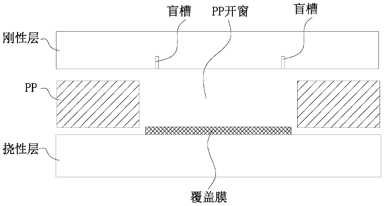
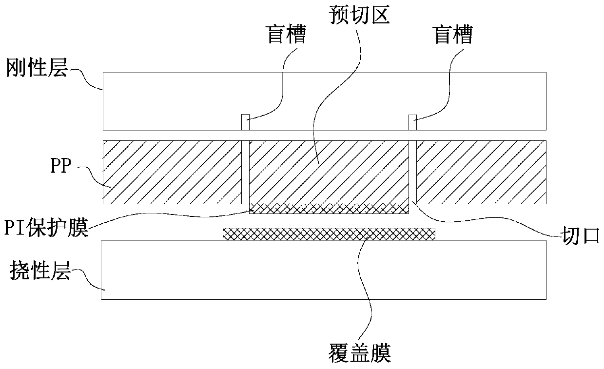
[0031] Making the rigid layer: as in the production process of the PCB in the prior art, the raw materials of the PCB are cut to obtain the rigid core board of the required size. Through the processes of film coating, exposure, development, etching and film stripping in sequence, the inner layer circuit is made on the rigid core board. Carry out OPE punching processing and AOI inspection of the inner layer of the rigid core board, and the qualified products enter the next process, that is, blind grooves around the edge of the cut-off area on the rigid core board, and the opening of the blind groove is set On the side opposite the flex board, the rigid core board is then browned.

[0032] Making the flexible layer: Like the production process of the flexible circuit board (FPC) in the prior...


PUM

PropertyMeasurementUnit
thicknessaaaaaaaaaa
thicknessaaaaaaaaaa

Abstract

The invention relates to the technical field of printed circuit boards, in particular to a manufacturing method of a rigid-flexible combined board. According to the invention, the press-fit structureis changed and a pp window does not need to be formed in a prepreg in the press-fit process; a PI protective film is attached to a pre-cutting area. During the press-fit process, the prepreg does notneed to be contracted inwards, so that the sufficient flowing adhesive is provided to ensure the bonding effect of the rigid-flexible layer and a problem of overflowing of the excessive flowing adhesive to the pp window, that is, binding to the flexible area is solved. Besides, with no PP window, a flatness problem of protruding or recession on the press-fit surface due to the window height falling difference caused by the PP window in the prior art is solved.

Description

technical field [0001] The invention relates to the technical field of printed circuit boards, in particular to a method for manufacturing a rigid-flex board. Background technique [0002] Rigid-flex boards, also known as soft-rigid boards, are composed of rigid boards and flexible boards that are selectively laminated together. Its structure is tight, and metallized holes are used to form conductive connections. The printed circuit board combining rigid and flexible materials makes full use of the characteristics of the flexible board and solves the problem of electrical connection with the rigid board. The flexible bonded board can be moved, bent, folded, twisted, and realize three-dimensional wiring, which greatly saves the installation space of electronic components and complies with the development trend of "light, thin, short, and small" electronic products. , aerospace, automotive electronics, medical electronics, consumer electronics and many other fields have been ...

Claims


Application Information

Patent Timeline
Patent Type & Authority Applications(China)
IPC IPC(8): H05K3/36H05K3/46
CPCH05K3/361H05K3/4611
Inventor 黄望望寻瑞平吴家培覃红秀何淼
Owner JIANGMEN SUNTAK CIRCUIT TECH
Why Eureka
Try Eureka