
Parallel photochemical reaction instrument

A photochemical reaction and parallel reaction technology, applied in chemical instruments and methods, chemical/physical processes, chemical/physical/physicochemical processes, etc., can solve problems such as increased manufacturing costs, increased use and maintenance costs, and redundant systems. Reduce manufacturing and maintenance costs, realize data visualization, simple and friendly operation

Pending Publication Date: 2020-01-14
上海善施科技有限公司
View PDF0 Cites 2 Cited by
  • Summary
  • Abstract
  • Description
  • Claims
  • Application Information

AI Technical Summary

Problems solved by technology

However, the reactor uses Kessil LED light source, which is high in power and expensive, and cannot be popularized, and it is not aimed at the international standard Shrek reaction tube, making it unable to serve chemists in a considerable number of countries and regions, such as mainland China. very low
At present, most of the photoreactors used in photocatalytic research laboratories using Shrek reaction tubes are self-made, simple and have potential safety hazards, which greatly reduces the repeatability of the reaction.
[0004] At present, the parallel photochemical reaction instrument of the prior art uses 8 sets of parallel reaction components and is equipped with a wifi module. In actual use, this parallel photochemical reaction instrument is bloated and the system is complicated. Interference, easy replacement of components, not only increases the manufacturing cost, but also increases the use and maintenance costs

Method used


Image

  • Parallel photochemical reaction instrument
  • Parallel photochemical reaction instrument
  • Parallel photochemical reaction instrument

Examples


Embodiment Construction

[0037] The preferred embodiments of the present invention will be described in detail below in conjunction with the accompanying drawings, and the present invention will be further elaborated.

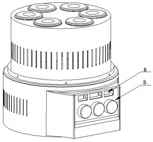
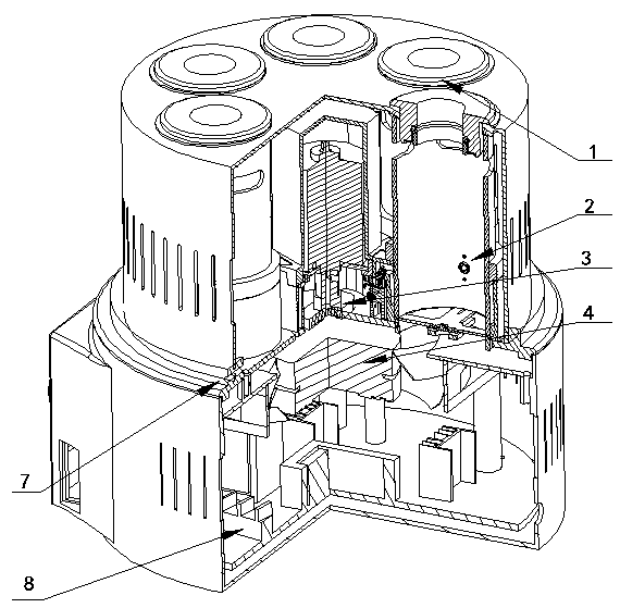
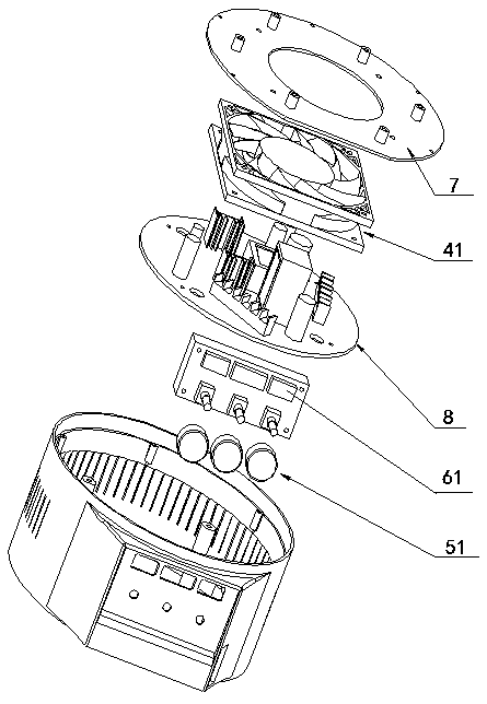
[0038] First, combine the Figure 1~8 The parallel photochemical reaction apparatus according to the embodiment of the present invention is used in the field of visible light parallel reaction experiments, and can also be used in the field of ordinary chemical experiments that do not require light sources, and has a wide range of application scenarios.

[0039] Such as Figure 1~3 As shown, a parallel photochemical reaction apparatus according to an embodiment of the present invention has a mounting plate 7 for supporting, a main board 8 for providing electric energy, and a reaction module 1, a light emitting module 2, a stirring module 3, a temperature control module 4, Control module 5 and display module 6. In this embodiment, when the light source is not needed for chemical reacti...


PUM


Abstract

The invention discloses a parallel photochemical reaction instrument. The parallel photochemical reaction instrument comprises a mounting plate and a main board, and further comprises a reaction module, a light emitting module, a stirring module, a temperature control module, a control module and a display module, wherein the reaction module is fixedly arranged on the mounting plate for a chemicalreaction; the light emitting module is fixedly arranged on the reaction module for providing parallel light; the stirring module is fixedly arranged on the mounting plate for providing stirring driving force for the chemical reaction; the temperature control module is fixedly arranged on the mounting plate for controlling the temperature of the chemical reaction; the control module is separatelyconnected with the light emitting module, the stirring module and the temperature control module for separately controlling the light emitting module, the stirring module and the temperature control module; and the display module is connected with the light emitting module, the stirring module and the temperature control module separately for displaying parameters of the light emitting module, thestirring module and the temperature control module. According to the parallel photochemical reaction instrument, the system design is simplified, parts are convenient to replace, the occupied space is reduced, data visualization is further realized, the operation is simpler and more friendly, and manufacturing and maintenance costs are greatly reduced.

Description

technical field [0001] The invention relates to a visible light parallel reaction experimental device, in particular to a parallel photochemical reaction instrument. Background technique [0002] As the greenest energy source, visible light has attracted more and more attention in recent years, especially in the field of organic synthesis. Traditional light-promoted organic reactions mainly use ultraviolet light. Since 2008, Macmillan, Yoon and Stephenson have reported a series of organic reactions promoted by visible light. For different reaction systems, photocatalysts can be used as both oxidants and reductants to achieve By understanding the electron transfer between catalysts and substrates, a series of organic synthesis methodological studies and synthesis of complex natural products have been developed under extremely mild conditions. Due to the mild conditions and easy operation of visible light catalysis, chemists have reported a lot of work on visible light cataly...

Claims


Application Information

Patent Timeline
Patent Type & Authority Applications(China)
IPC IPC(8): B01J19/12B01J19/00
CPCB01J19/127B01J19/0053B01J19/0013B01J2219/00051
Inventor 姜雪峰李一鸣赛义德.阿里.里兹维张飞杭
Owner 上海善施科技有限公司
Learn More