Galvanometer correction system and correction method thereof

A technology of correction system and correction method, which is applied in the field of additive manufacturing, can solve the problems of time-consuming, galvanometer correction, high cost, etc., and achieve the effect of low cost, high precision and high precision correction

Inactive Publication Date: 2020-01-14
XIAN BRIGHT ADDTIVE TECH CO LTD
View PDF6 Cites 10 Cited by
  • Summary
  • Abstract
  • Description
  • Claims
  • Application Information

AI Technical Summary

Problems solved by technology

[0004] The purpose of the present invention is to provide a vibrating mirror calibration system to solve the problem that the vibrating mirror calibration system needs to use auxiliary measuring equipment, which leads to high cost, time-consuming, complicated operation and the inability to calibrate the vibrating mirror at any time

Method used


Image

  • Galvanometer correction system and correction method thereof
  • Galvanometer correction system and correction method thereof
  • Galvanometer correction system and correction method thereof

Examples


Embodiment Construction

[0055] The present invention will be described in detail below in conjunction with the accompanying drawings and specific embodiments.

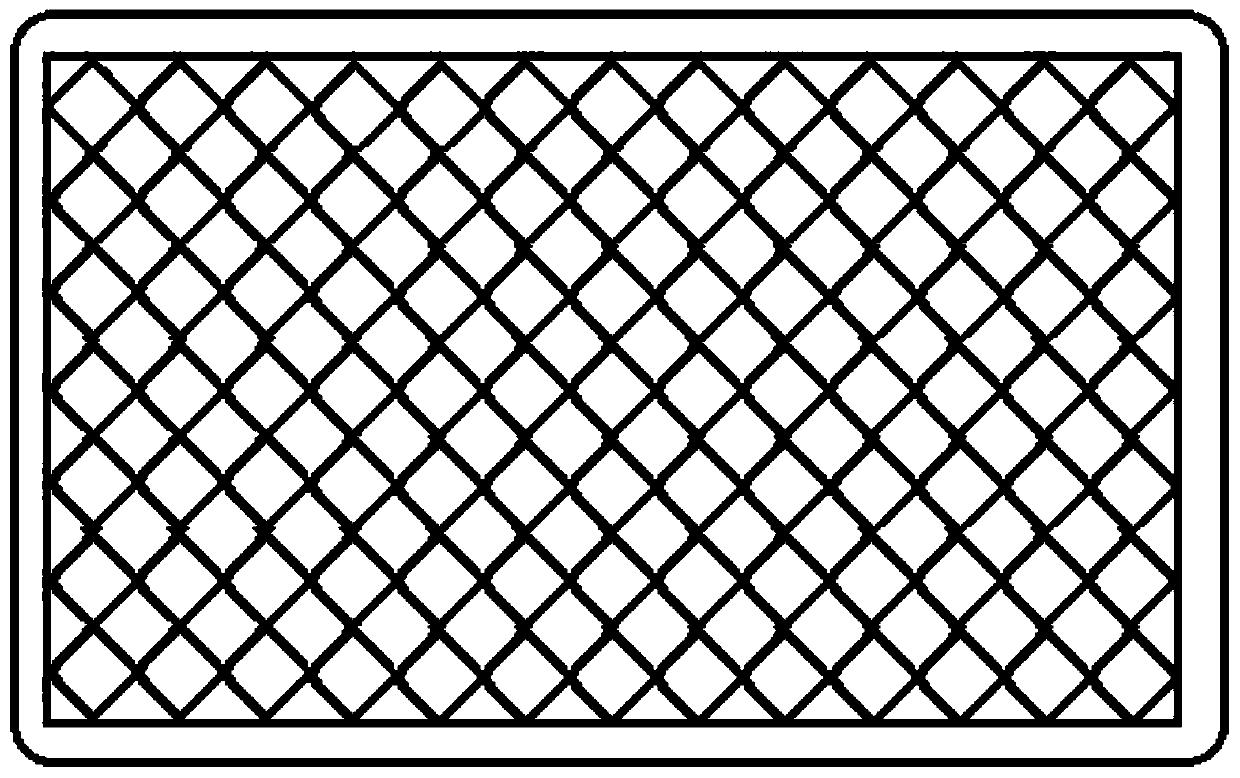
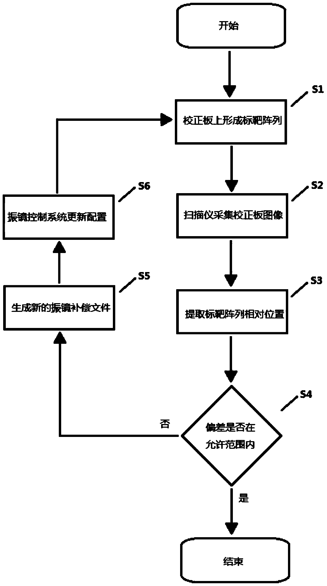
[0056] The galvanometer calibration system provided by the present invention uses a contact scanner to collect images of the target array on the galvanometer calibration board, and after processing the collected target array through the image processing module, the galvanometer compensation is output to correct the galvanometer ; Without the aid of auxiliary measuring equipment, the galvanometer can be calibrated with low cost, high efficiency and high precision.

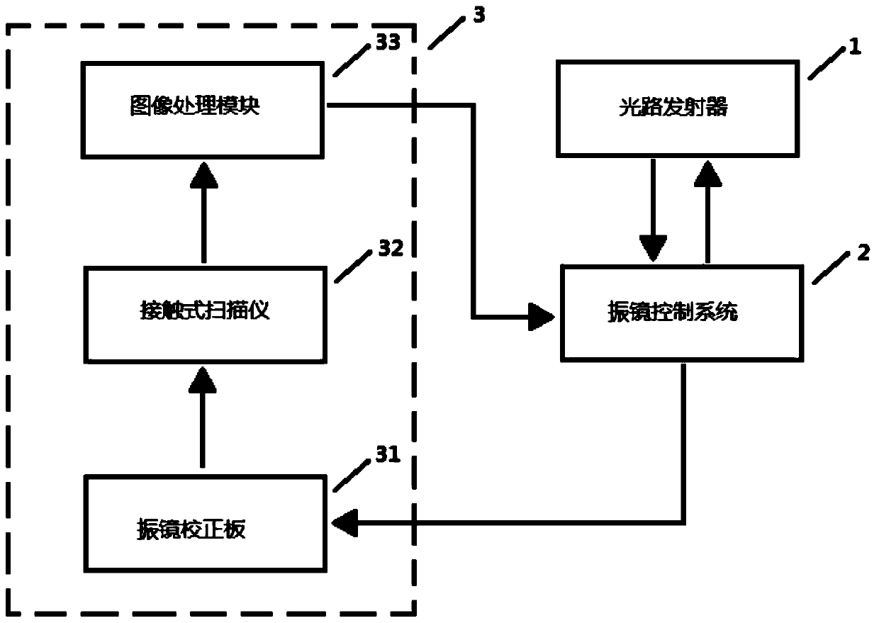
[0057] figure 1 The module structure of the vibrating mirror correction system provided by the present invention is shown, specifically as follows:

[0058] The galvanometer correction system includes an optical path transmitter 1 for emitting a light beam;

[0059] The vibrating mirror control system 2 is used to control the deflection of the light beam emitted by the optical pa...


PUM


Abstract

The invention discloses a galvanometer correction system. The galvanometer correction system comprises an optical path transmitter, a galvanometer control system and a galvanometer correction system.The optical path transmitter is used for transmitting light beams; the galvanometer control system is used for controlling the light beams transmitted by the optical path transmitter to deflect and mark a target array and sintering the target array on the galvanometer correction system; the galvanometer correction system is used for receiving the light beams transmitted by the optical path transmitter so as to form the target array and generate a galvanometer compensation file. The galvanometer correction system comprises a contact-type scanner, and two sets of parallel inclined lines fixed atintervals are embossed at the outer side of a light-transmission glass plate of the scanner and are in perpendicular intersection to form multiple evenly-arrayed cross points. The invention further discloses a correction method of the galvanometer correction system. The contact-type scanner is used for conducting image collection on the target array on a galvanometer correction plate, the collected target array is processed through an image processing module, and galvanometer compensation is output for correcting the galvanometer. Without assistance of auxiliary measurement equipment, the galvanometer can be corrected with low cost, high efficiency and high precision.

Description

technical field [0001] The invention belongs to the technical field of additive manufacturing, relates to a vibrating mirror correction system, and also relates to a correction method using the vibrating mirror correction system. Background technique [0002] In the field of additive manufacturing technology, the galvanometer is generally used to control the light (laser, etc.) path to irradiate the powder (metal, resin, etc.) to solidify it to form complex parts; environmental changes such as temperature, humidity, vibration, and mechanical wear of the motor, etc. , causing the galvanometer motor to lose steps, and a deviation will occur after a certain period of time, which will affect the molding quality of the part. Therefore, it is necessary to perform error compensation on the galvanometer in time to reduce the deviation. [0003] In the field of additive manufacturing technology, the target array is usually printed on the calibration plate, and then the expensive auxi...

Claims


Application Information

Patent Timeline
Patent Type & Authority Applications(China)
IPC IPC(8): B23K26/064B23K26/082B23K26/70B29C64/10B29C64/153B29C64/268B22F3/105
CPCB22F3/105B23K26/064B23K26/082B23K26/70B23K26/702B29C64/10B29C64/153B29C64/268Y02P10/25
Inventor 范美极杨东辉袁佐鹏
Owner XIAN BRIGHT ADDTIVE TECH CO LTD
Why Eureka
Try Eureka