Multilayer geotextile synchronous combination forming equipment

A composite molding, geotextile technology, applied in the directions of lamination, lamination device, control lamination, etc., can solve the problems of limited fiber fineness of geotextiles, thin geotextiles, damage to single-layer geotextiles, etc.

Inactive Publication Date: 2020-01-14
ANHUI SCI & TECH UNIV
View PDF4 Cites 5 Cited by
  • Summary
  • Abstract
  • Description
  • Claims
  • Application Information

AI Technical Summary

Problems solved by technology

[0003] Nonwoven geotextiles are widely used in water conservancy, electric power, highways, railways, airports, ports, reclamation, environmental protection, flood control, and various underground and underwater civil engineering because of their good elongation, mechanical properties, and horizontal permeation and filtration properties. In the field of engineering, at present, the geotextiles used in filtration and reverse filtration applications are mostly single-layer geotextiles, and are affected by the particle size of the soil particles and the particle size of the gravel in the use environment, resulting in the fiber fineness of the geotextiles being limited. As a result, the thickness of the geotextile is limited, which in turn leads to a thin geotextile that is easily damaged during use
[0004] At present, single-layer geotextiles are widely used, but there are still many shortcomings in single-layer geotextiles. In some places, it is easy to cause damage to single-layer geotextiles and cannot play a good role. Therefore, it is necessary to design a A device in which the geotextiles are combined together, which not only makes the geotextiles less prone to damage, but also improves work efficiency

Method used


Image

  • Multilayer geotextile synchronous combination forming equipment
  • Multilayer geotextile synchronous combination forming equipment
  • Multilayer geotextile synchronous combination forming equipment

Examples


Embodiment Construction

[0030] The technical solutions of the present invention will be further described below in conjunction with the accompanying drawings and through specific implementation methods.

[0031] Wherein, the accompanying drawings are only for illustrative purposes, showing only schematic diagrams, rather than physical drawings, and should not be construed as limitations on this patent; in order to better illustrate the embodiments of the present invention, some parts of the accompanying drawings will be omitted, Enlargement or reduction does not represent the size of the actual product; for those skilled in the art, it is understandable that certain known structures and their descriptions in the drawings may be omitted.

[0032] In the drawings of the embodiments of the present invention, the same or similar symbols correspond to the same or similar components; , "inner", "outer" and other indicated orientations or positional relationships are based on the orientations or positional ...


PUM


Abstract

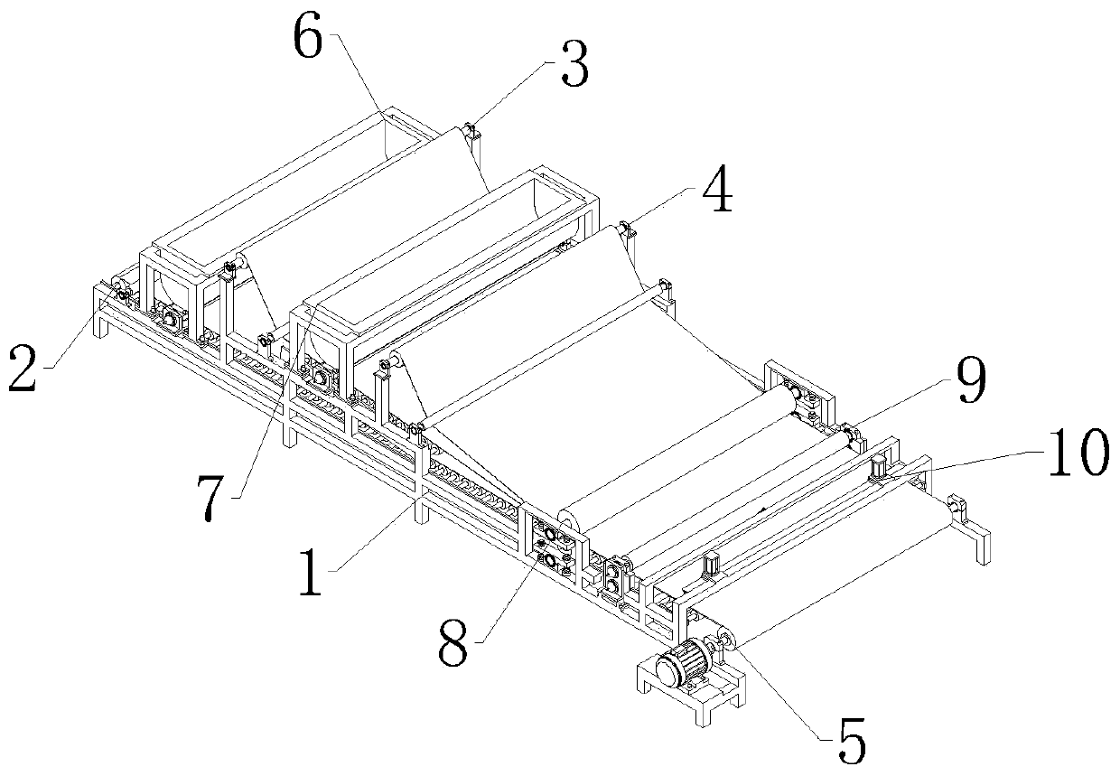
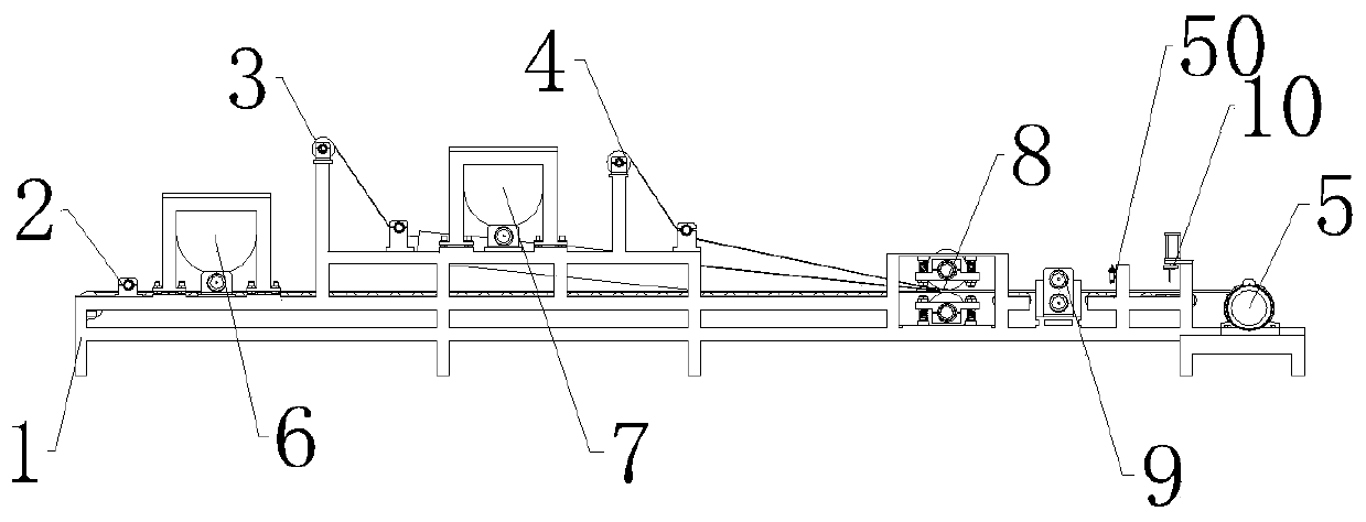
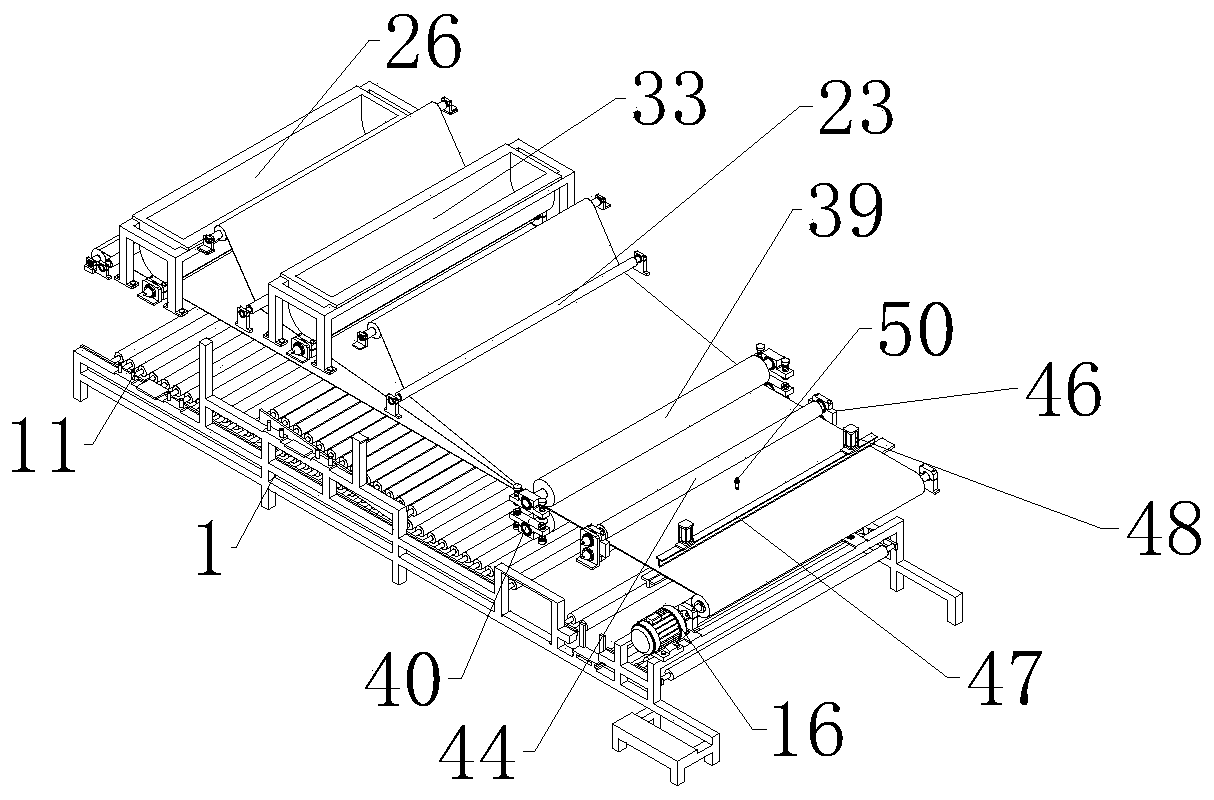
The invention relates to the field of geotextile and in particular relates to multilayer geotextile synchronous combination forming equipment which comprises a bracket as well as a feeding component,a gluing component, a combination component, a heating component and a trimming component, wherein the feeding component is arranged above the bracket; the gluing component is arranged at the top of the bracket; the combination component is arranged on one side of the gluing component; the heating component is arranged on one side far away from the gluing component, of the combination component; the trimming component is arranged on one side far away from the combination component, of the heating component; the feeding component comprises a first feeding mechanism, a second feeding mechanism,a third feeding mechanism and a transmission mechanism; the gluing component comprises a first gluing mechanism and a second gluing mechanism; and the feeding component, the gluing component, the combination component, the heating component and the trimming component are arranged in sequence in a straight line along the length direction of the bracket. By adopting the equipment, the problem that single-layer geotextile is easily damaged can be solved, the pressure resistance of the geotextile can be improved, and the working efficiency can be improved.

Description

technical field [0001] The invention relates to the field of geotextiles, in particular to a multi-layer geotextile synchronous composite molding device. Background technique [0002] Geotextile is a new type of building material. The raw material is polyester, polypropylene, acrylic, nylon and other polymer synthetic fibers. According to the manufacturing method, it is divided into two types: woven geotextile and non-woven geotextile. The general engineering is mainly The non-woven geotextiles used have multiple functions such as anti-seepage, reverse filtration, drainage, isolation, reinforcement, protection, and sealing. Compared with the anti-seepage effect of conventional masonry and concrete materials, it has low investment and high construction efficiency. The process is simple, the construction period is short, the anti-seepage effect is good, and the channel utilization coefficient is high. Geotextile is a widely used geosynthetic material. Isolation of hydraulic s...

Claims


Application Information

Patent Timeline
IPC IPC(8): B32B37/12B32B37/10B32B37/06B32B43/00B32B41/00
CPCB32B37/0053B32B37/06B32B37/10B32B37/1284B32B41/00B32B43/003
Inventor 魏宝丽夏轩夏显明陈丰张华
Owner ANHUI SCI & TECH UNIV
Why Eureka
Try Eureka