
System for autonomously limiting, recovering and releasing marine navigation device

A technology of aircraft and ocean, which is applied in the system field of self-limiting and retracting marine aircraft, can solve the problems of personnel injury equipment, high use and maintenance costs, and high risk, so as to improve operating efficiency, reduce economic costs, Highly intelligent effect

Active Publication Date: 2020-01-14
HARBIN ENG UNIV
View PDF7 Cites 1 Cited by
  • Summary
  • Abstract
  • Description
  • Claims
  • Application Information

AI Technical Summary

Problems solved by technology

[0003] At present, there are generally three methods for the recovery of marine unmanned aerial vehicles. The first method is for professionals to take a small boat close to the underwater robot carrier and perform manual lifting and docking to complete the recovery operation. Personnel injury and equipment damage; the second is to complete the recovery of the carrier with the help of a dedicated aircraft recovery system, such as a crane-type and frame-type recovery system. This recovery system has a complex structure and cannot autonomously limit the position of the aircraft. 1. It has high requirements on the mother ship, and the use and maintenance costs are relatively large; the third is to make the aircraft automatically throw the cable on the water surface during recovery, and the operators on the mother ship will salvage the cable and perform corresponding operations. Rope devices generally use pyrotechnics and high-pressure gas cylinders as power sources, which have problems such as high risk, high cost, and complicated operation.

Method used


Image

  • System for autonomously limiting, recovering and releasing marine navigation device
  • System for autonomously limiting, recovering and releasing marine navigation device

Examples


Embodiment Construction

[0016] The present invention will be further described in detail below in conjunction with the accompanying drawings and specific embodiments.

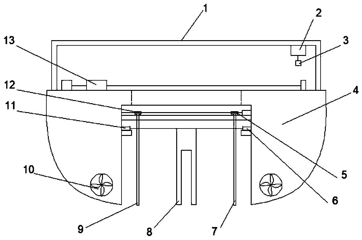
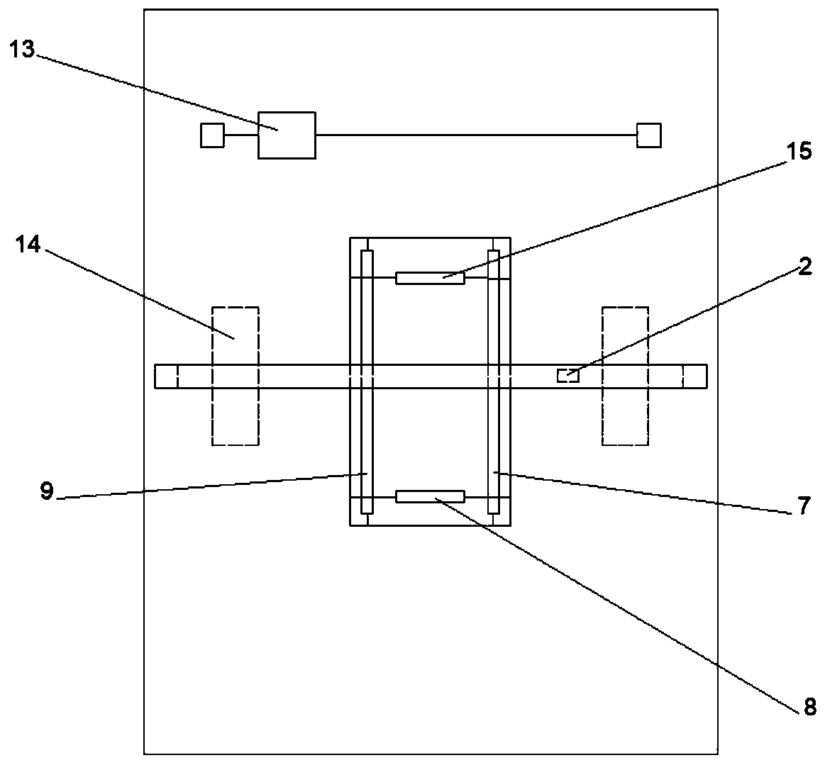
[0017] Such as Figure 1-2 As shown, including: 1. Crane beam, 2. Bridge car B, 3. Electromagnetic lifting head, 4. Catamaran platform, 5. Starboard side fixed claw sliding trolley, 6. Tail fixed claw rotating device, 7. Starboard side Fixed claw, 8. Tail fixed claw, 9. Port side fixed claw, 10. Differential propeller, 11. Tail fixed claw rotating device, 12. Port side fixed claw sliding trolley, 13. Anti-roll slider, 14. Watertight Compartment, 15. Bow fixing claws.

[0018] The invention belongs to the field of marine unmanned vehicles, and in particular relates to a system for autonomously limiting and retracting marine vehicles. The purpose of the invention is to provide a system for autonomously limiting and retracting the marine craft with simple operation, high intelligence and good reliability.

[0019] For realizing the pu...


PUM


Abstract

The invention belongs to the field of marine unmanned navigation devices, and aims to provide a system for autonomously limiting, recovering and releasing a marine navigation device. An electromagnetic crane and a sliding block stabilizer are mounted on a catamaran platform; a bow fixing claw and a stern fixing claw are controlled by a bow fixing claw rotating device and a stern fixing claw rotating device to be mounted in the middle of the catamaran platform; a larboard side fixing claw and a starboard side fixing claw are controlled by a larboard side fixing claw sliding trolley and a starboard side fixing claw sliding trolley to be mounted on the catamaran platform; and two differential thrusters are mounted at the bottom of the catamaran platform. By the aid of the system, the navigation device can be guided and limited autonomously, so that the accuracy is greatly improved; the navigation device is limited by the aid of the four surrounding fixing claws, so that collisions of thenavigation device and a mother ship are reduced; by the aid of the stabilizer at the front part of a deck, the recovery mother ship can keep balance under severe sea conditions; and through the watertight design of an inside cabin of the mother ship, multiple navigation devices can be recovered and stored simultaneously, so that the operation efficiency is greatly improved.

Description

technical field [0001] The invention belongs to the field of marine unmanned vehicles, and in particular relates to a system for autonomously limiting and retracting marine vehicles. Background technique [0002] The marine unmanned vehicle is a marine robot that can independently perform designated tasks in the ocean. It is mainly used in many fields such as marine technology, marine scientific investigation and research, marine environment monitoring, seabed exploration, and marine building inspection. When the aircraft completes the designated task, it needs to be released from the mother ship first, and then recovered after completing the task. Due to the complex and changeable marine environment, especially when the sea conditions are poor, the recovery of marine aircraft will be more difficult. Especially for the recovery of multi-vehicle formations, so fast, efficient and reliable recovery of multi-vehicles is an important research content in the field of marine unman...

Claims


Application Information

Patent Timeline
IPC IPC(8): B63B23/40B63B23/62
CPCB63B23/40B63B23/62
Inventor 牛广智万磊秦洪德邹劲
Owner HARBIN ENG UNIV
Features
  • Generate Ideas
  • Intellectual Property
  • Life Sciences
  • Materials
  • Tech Scout
  • Unparalleled Data Quality
  • Higher Quality Content
  • 60% Fewer Hallucinations
Learn More