

High-dynamic centrifuge overload simulation test device
A simulation test and high dynamic technology, applied in the direction of aircraft component testing, etc., can solve the problems of inability to simulate the overload of the aircraft, limited movement space, and limited slack of the rope traction device, so as to solve the coupling problem of attitude and overload, increase the Large movement space, solving the effect of complex structure
- Summary
- Abstract
- Description
- Claims
- Application Information
AI Technical Summary
Problems solved by technology
Method used
Image

Examples
Embodiment 1
[0051] Example 1, such as figure 1 shown;
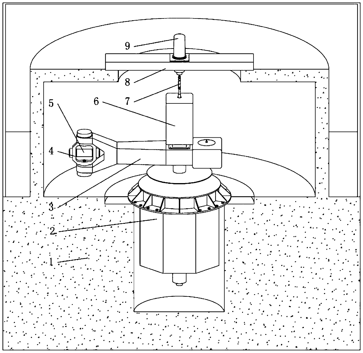
[0052] A high dynamic centrifugal overload simulation test device, comprising:
[0053] A first degree of freedom device that provides static overload for the test piece 5;
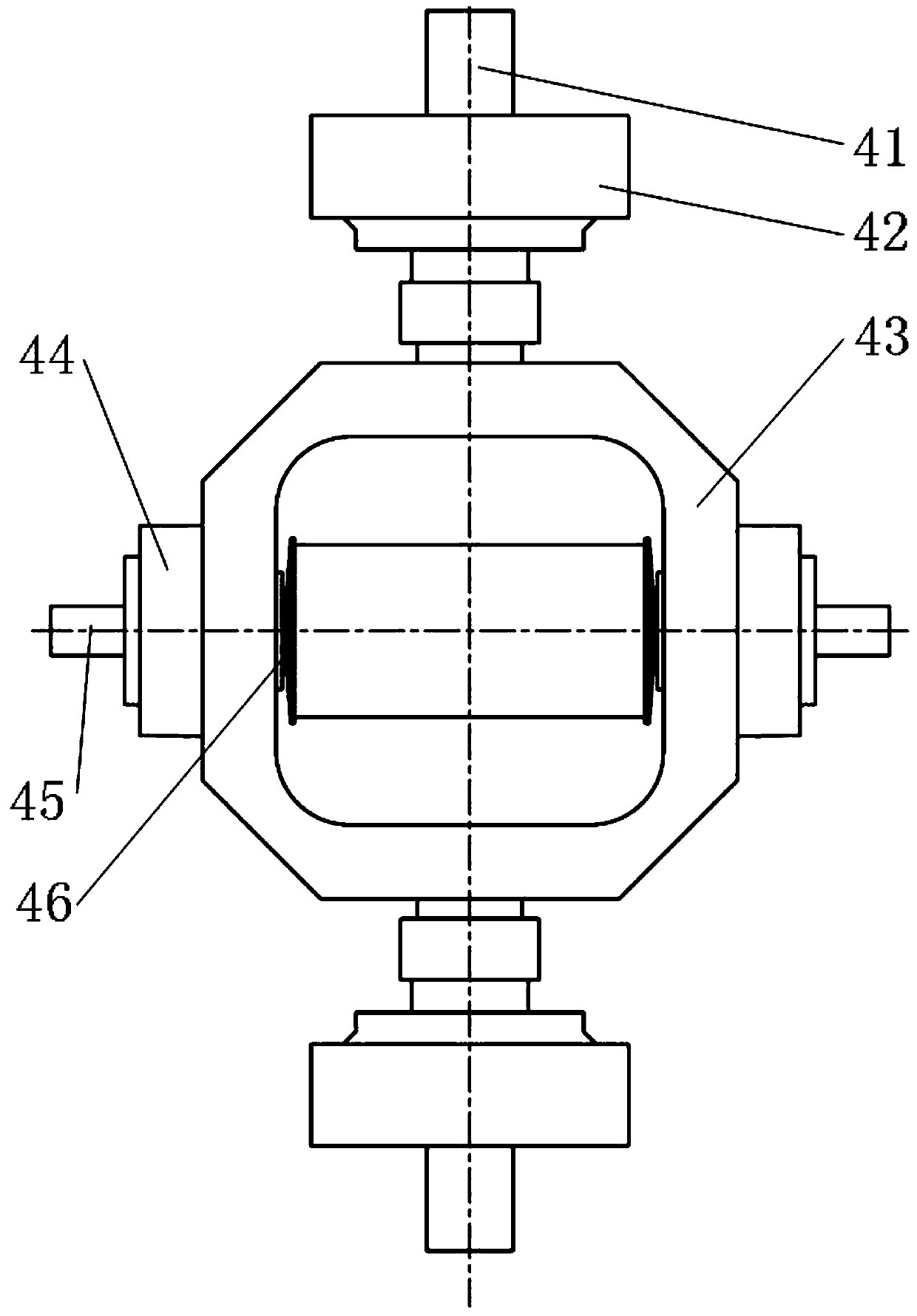
[0054] A second degree of freedom device 4 that provides yaw rotation motion for the test piece 5;
[0055] It is the third degree of freedom device for the rolling and rotating motion of the test piece 5; the test piece 5 is placed on the third degree of freedom device, and the second degree of freedom device 4 is used for the degree of freedom control of the third degree of freedom device; the first degree of freedom device It is used for the degree of freedom control of the second degree of freedom device 4 .
Embodiment 2
[0056] Example 2, such as figure 1 shown;
[0057] The difference between this embodiment and Embodiment 1 is that the first degree of freedom device includes:
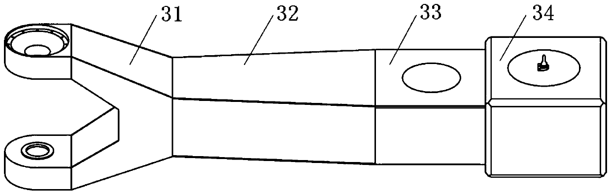
[0058] An active power mechanism for driving the main arm system 3 to rotate;
[0059] The main arm system 3 ; the power output end of the power mechanism is connected with the main arm system 3 .
[0060] As a power element, the active power mechanism is arranged at the bottom of the structure, adopts direct drive mode, and is directly connected with the main arm system 3 to realize centrifugal rotation movement, which reduces other transitional connection structures and shortens the power transmission path; and the upper end of the main power mechanism is passed through the screw It is connected with the civil foundation 1 to carry the main boom system 3 and its upper parts, avoiding adding redundant bearing mechanisms and shortening the axial dimension of the whole machine. This arrangement makes the whole machi...
Embodiment 3
[0061] Example 3, such as figure 1 shown;
[0062] The difference between this embodiment and Embodiment 1 is that the first degree of freedom device also includes:
[0063]Civil engineering foundation 1; civil engineering foundation 1 is formed as upper and lower layers (here refers to the upper and lower layers of cavities), in which the active power mechanism is fixedly placed on the lower layer of civil engineering foundation 1; here generally refers to the active force The shell part of the mechanism is fixedly installed on the foundation;
[0064] The instrument cabin 6; the instrument cabin 6 is placed on the upper part of the rotation center of the main arm system 3; it is generally fixed installation here;
[0065] The universal coupling 7; the instrument cabin 6, the universal coupling 7, the second degree of freedom device 4, and the third degree of freedom device are placed on the upper layer of the civil foundation 1; the connection between the universal couplin...
PUM
 Abstract
Description
Claims
Application Information