Oil spilling collecting device and method

A collection device and oil spill technology, which is applied in general water supply conservation, water conservancy projects, and open water surface cleaning, etc., can solve the problems of good marine oil spill collection effect, poor oil spill collection effect, etc., and achieves good scraping effect, Complete collection and good collection effect

Active Publication Date: 2020-01-14
THE FIRST INST OF OCEANOGRAPHY SOA
View PDF9 Cites 6 Cited by
  • Summary
  • Abstract
  • Description
  • Claims
  • Application Information

AI Technical Summary

Problems solved by technology

[0003] The present invention overcomes the deficiency that the marine oil spill collection device has poor oil spill collection effect, and provides an oil spill collection device and method, which has a good marine oil spill collection effect

Method used


Image

  • Oil spilling collecting device and method
  • Oil spilling collecting device and method
  • Oil spilling collecting device and method

Examples


Embodiment 1

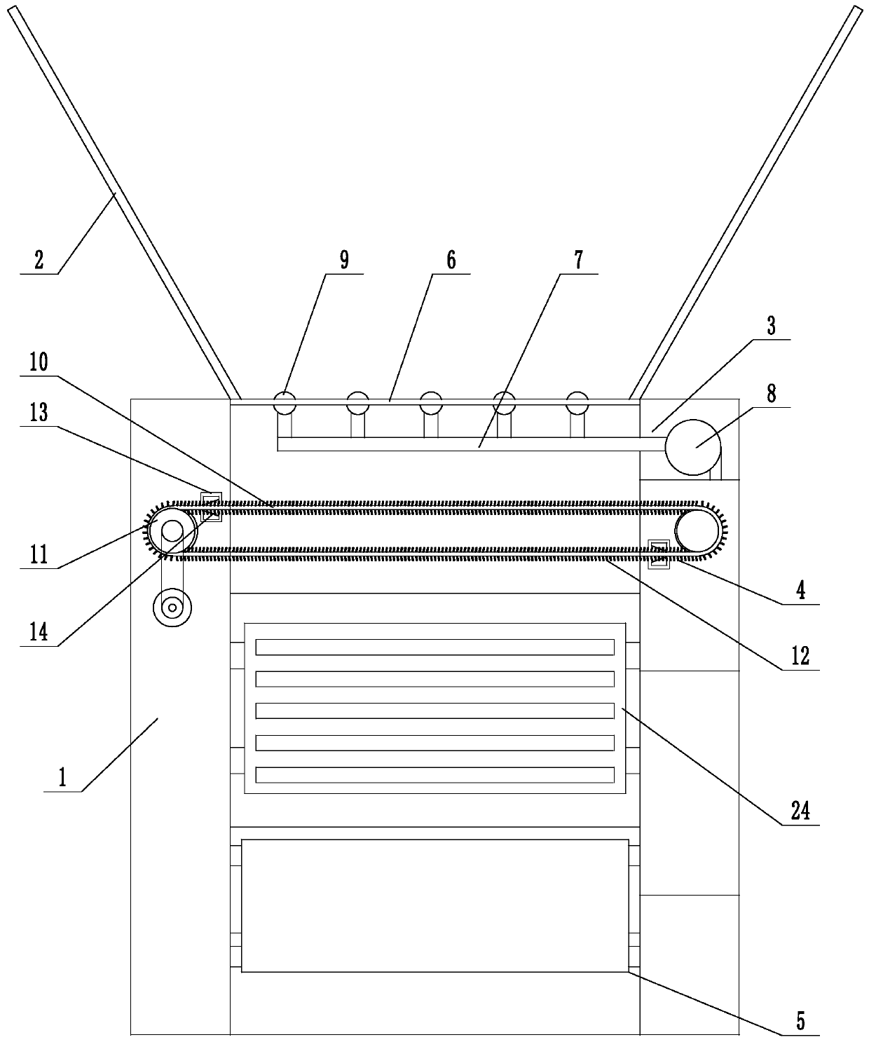
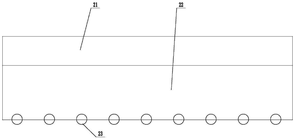
[0023] Example 1: An oil spill collection device (see attached figure 1 Attached image 3 ), including two oppositely arranged floating bodies 1, an oil guide float rod connected to the front end of the floating body 2, an oil suction mechanism 3, a front stage collection mechanism 4, a rear stage collection mechanism 5, and an oil suction mechanism installed between the two floating bodies from front to back. It includes a floating beam 6, an oil suction pipe 7, and an oil suction pump 8, which are placed between the two floating bodies. A row of suction heads 9 are installed on the floating beam. The suction heads are all connected to the oil suction pipe, and the oil suction pipe is connected to the suction pump; the front-stage collection mechanism includes a collection rope 10. Two guide wheels 11, the collection rope drive is connected between the two guide wheels, the collection rope is placed on the water, one guide wheel is connected to the output shaft of the front-stag...

Embodiment 2

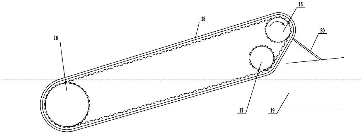
[0026] Example 2: An oil spill collection device (see attached figure 1 Attached Figure 4 ), its structure is similar to embodiment 1, the main difference is that the three-dimensional collection mechanism 24 is installed between the front-stage collection mechanism and the rear-stage collection mechanism in this embodiment. The three-dimensional collection mechanism includes an upper wheel 25, a lower wheel 26, and a driving wheel 27. , The upper wheel, the lower wheel, and the driving wheel are connected with a transmission belt 28 for transmission. The driving wheel is connected to the output shaft of the driving motor. The upper wheel and the driving wheel are placed above the water surface, the lower wheel is placed in the water, and the lower wheel is placed in front of the upper wheel. Below, the outer surface of the transmission belt is connected with a number of oil-bearing plates 29 at intervals. The oil-bearing plates are densely covered with a number of fine filteri...


PUM


Abstract

The invention discloses an oil spilling collecting device and method, and aims at solving the problem that an ocean oil spilling collecting device is poor in oil spilling collecting effect. The devicecomprises two oppositely-arranged floating bodies, oil guiding floating rods connected to the front ends of the floating bodies, an oil suction mechanism, a preceding-stage collecting mechanism and abackward-stage collecting mechanism. The oil suction mechanism comprises a floating beam, an oil suction pipe and an oil suction pump. A row of oil suckers are installed on the floating beam, the oilsuckers are all communicated with the oil suction pipe, and the oil suction pipe is connected with the oil suction pump; the preceding-stage collecting mechanism comprises a collecting rope and two guiding wheels, the collecting rope is in transmission connection between the two guiding wheels, one guiding wheel is in transmission connection with a preceding-stage motor output shaft, a pluralityof oil suction rope heads are densely distributed on the collecting rope, an oil scraping box is installed on each floating body, a cone frustum shaped oil scraping hole is formed inside each oil scraping box, and the collecting rope penetrates through the oil scraping hole; and the backward-stage collecting mechanism comprises a driving wheel, a driven wheel, a tensioning wheel and an oil suctionconveyor belt, an oil receiving groove is formed between the two floating bodies, a scraper plate is connected to the oil receiving groove, and the end of the scraper plate abuts against the outer surface of the oil suction conveyor belt.

Description

Technical field [0001] The invention relates to a marine oil spill collection technology, more specifically, it relates to an oil spill collection device and method. Background technique [0002] Marine oil spill is one of marine environmental pollution. Although the ocean has the ability to purify oil pollution, it is not unlimited. The pollution caused by oil entering the ocean is very serious to the marine environment and marine living resources. Generally, the complete oxidation of 1 liter of oil requires the consumption of 400,000 liters of dissolved oxygen in seawater. Therefore, a large-scale oil spill pollution accident can cause severe hypoxia in a large area of ​​the sea, killing a large number of fish, shrimp and seabirds, or causing economic fish, Shrimp and shellfish produce oily odor, which reduces the edible value of seafood. The oil slick was washed to the coast by the waves, contaminating the beach, causing the beach to be barren, destroying aquaculture and sal...

Claims


Application Information

Patent Timeline
Patent Type & Authority Applications(China)
IPC IPC(8): E02B15/10
CPCE02B15/106Y02A20/204
Inventor 刘伟峰姜伟刘大海
Owner THE FIRST INST OF OCEANOGRAPHY SOA
Why Eureka
Try Eureka